#1 · Aug 18, 2008 21:46 UTC
I'm covering this amp, per an earlier request... it's a good topology to take a look at, and review, in light of the other stuff we've taken a quick look at over the past few days. There's been a LOT of information flowing, so hang tight, we'll check this one out, too. :-)
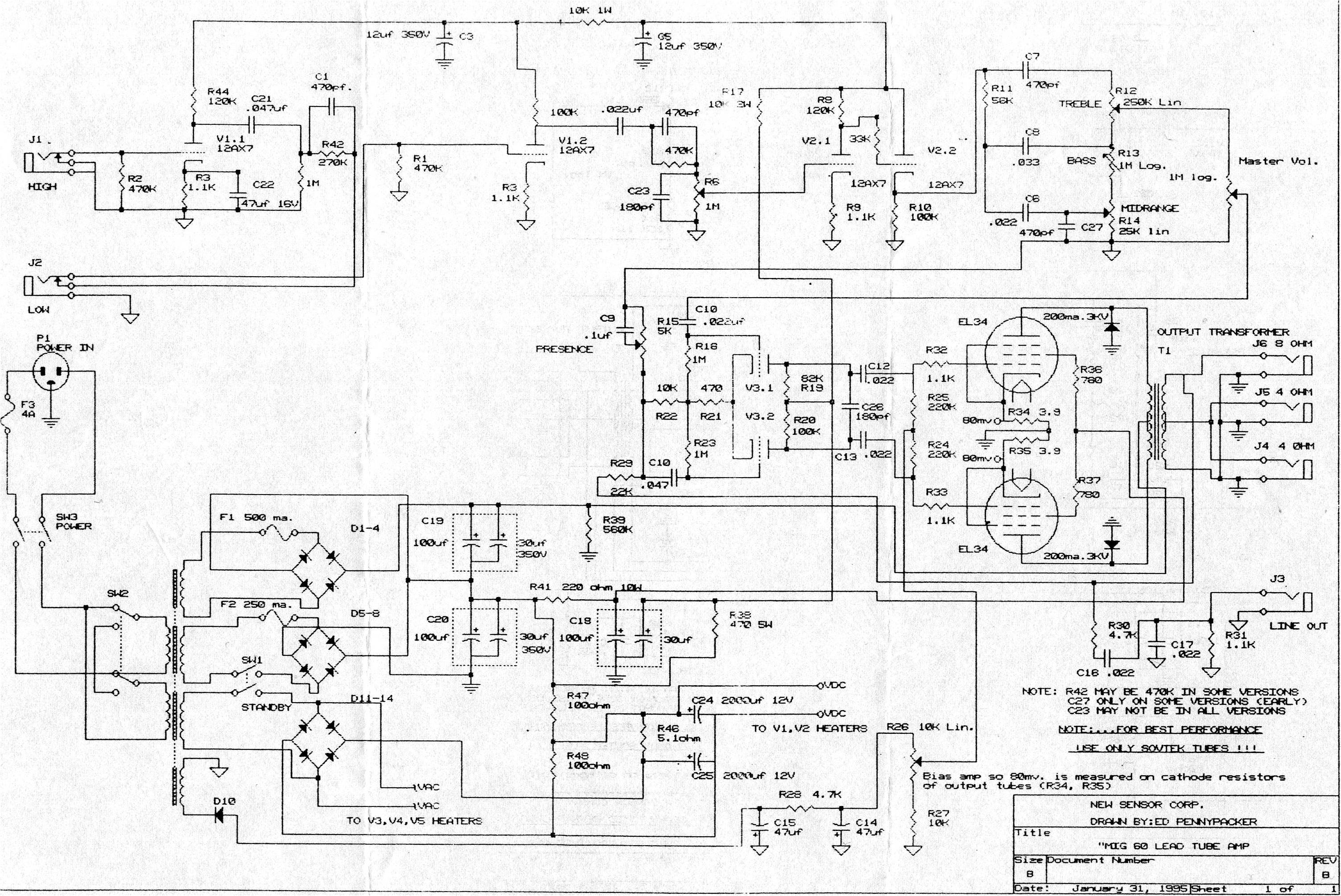
The MIG60 is a pretty standard topology, overall. The input impedance, on this amp, is slightly less than 1/2 of that of other amps we've looked at, at 470K rather than 1M. For guitars, there shouldn't be much difference, overall, in the final result. There is no grid-block resistor, here, either, indicating that this amp was designed with guitars in mind. If there were other electronic instruments that this amp were designed for, this amp would incorporate the 68K grid-block resistor.
The first stage (V1.1) is a flat frequency response, relatively high gain stage (higher than Fenders, with a 1.1K cathode bias resistor). This stage obtains even higher gain through the use of the cathode bypass capacitor, which has a high value.The output of the stage is coupled to a 1M resistor and then sent through C1/R42).
Looking at the values, in the schematic (270K/470pF) and reading the notes in the lower right, this is probably, on most amps, the same values as that in the Marshall amps 470K/470pF with a 720Hz high-pass filter. If the 270K resistor is employed this shelf frequency rises to 1.25kHz.
The 2nd stage (V1.2) is, again, a "hotter" stage, with another 1.1K resistor, here. Unlike stage 1, this stage is not bypassed, thus the signal gain is not quite as high as stage 1. The output, here, is coupled, again, through a 470K/470pF high-pass filter (720Hz) as per the Marshall standard. Now, rather than couple the top leg of the "Gain" pot, which is a stage "later" in this amp, than the Marshalls, to the wiper, Sovtek decided to place a 180pF capacitor across the "Gain" pot. This is a "low pass filter" with a center frequency around 885Hz - "bleeding" everything off above that frequency and "dulling" the previous stage output, just a bit.
The output of the "Gain" pot is fed into stage 3 (V2.1) which again, is biased slightly "hot", no cathode bypass and the output of which feeds directly into a cathode follower (V2.2) which feeds the tone stack.
The tone stack, in this amp, is a "hodge-podge" of stuff. The potentiometers, used here, are the same values as the Fender/Marshall stacks so the Treble frequency range, acted on by the 470pF capacitor (C7) and the various control settings is about the same as the Marshall amps. The 56K slope resistor is slightly larger than that of the Marshall "shifting" the "balance" of high and low frequencies slightly more in favor of the highs than the Marshall and the larger capacitor feeding the "Bass" portion of this circuit (C8/.033uF) ensures that all the bass frequencies that are fed here, get through. The "Middle" control still acts on the same frequency range as the standard Marshall. C27 is placed, according to the notes, only on select amps. If it is there, it provides additional high frequency roll-off to deepen the "mid-cut" on the amp. The output of the tone stack is pushed into a 1M "Master Vol" pot which then feeds the power stage.
The power stage is a standard EL34-based power stage, push-pull, biased midway between hot, and not. Nothing special, really, here. The feedback loop, on this amp, is tapped off the 8-ohm output and fed back into the phase splitter and that, largely, is it.
There are some distinctive differences between this, and a Marshall. In the Marshall amps, most of the distortion is generated in stage 3 of the amp, with some of the distortion being generated in Stage 2 and virtually none in Stage 1. The Marshalls typically run their first two stages pretty "cold" while this one is running those two stages relatively "hot", in terms of bias.
As considerable distortion is being generated in stages 2 and 3, I believe that's why they're using the "Treble bleed" across the volume pot - to suppress some of the potential noise and "fizz" as a result of a more symmetrical distortion that's being created by distortion more, or less, equally, in several stages, rather than a single stage which would be more asymmetric and a bit more "crunchy" without the "fizz" of this, more, symmetrical distortion.
In a nutshell, that's the "voice" of this amp and how they created it. In the Marshall amps, the "Gain" control is inserted between stages 1/2 rather than stages 2/3. This allows more control over the amount of distortion generated by the amp. The Gain, on this amp, is fixed between stages 1/2 and the input signal will determine more of the amount of drive, than the actual "Gain" control itself. The "Gain", in this topology" would only control how much more gain will be provided above that which has already been generated in stage 2.
Lots of different ways to do something, and this is just one good example of that.
Let me know if you have questions.
Dar
The MIG60 is a pretty standard topology, overall. The input impedance, on this amp, is slightly less than 1/2 of that of other amps we've looked at, at 470K rather than 1M. For guitars, there shouldn't be much difference, overall, in the final result. There is no grid-block resistor, here, either, indicating that this amp was designed with guitars in mind. If there were other electronic instruments that this amp were designed for, this amp would incorporate the 68K grid-block resistor.
The first stage (V1.1) is a flat frequency response, relatively high gain stage (higher than Fenders, with a 1.1K cathode bias resistor). This stage obtains even higher gain through the use of the cathode bypass capacitor, which has a high value.The output of the stage is coupled to a 1M resistor and then sent through C1/R42).
Looking at the values, in the schematic (270K/470pF) and reading the notes in the lower right, this is probably, on most amps, the same values as that in the Marshall amps 470K/470pF with a 720Hz high-pass filter. If the 270K resistor is employed this shelf frequency rises to 1.25kHz.
The 2nd stage (V1.2) is, again, a "hotter" stage, with another 1.1K resistor, here. Unlike stage 1, this stage is not bypassed, thus the signal gain is not quite as high as stage 1. The output, here, is coupled, again, through a 470K/470pF high-pass filter (720Hz) as per the Marshall standard. Now, rather than couple the top leg of the "Gain" pot, which is a stage "later" in this amp, than the Marshalls, to the wiper, Sovtek decided to place a 180pF capacitor across the "Gain" pot. This is a "low pass filter" with a center frequency around 885Hz - "bleeding" everything off above that frequency and "dulling" the previous stage output, just a bit.
The output of the "Gain" pot is fed into stage 3 (V2.1) which again, is biased slightly "hot", no cathode bypass and the output of which feeds directly into a cathode follower (V2.2) which feeds the tone stack.
The tone stack, in this amp, is a "hodge-podge" of stuff. The potentiometers, used here, are the same values as the Fender/Marshall stacks so the Treble frequency range, acted on by the 470pF capacitor (C7) and the various control settings is about the same as the Marshall amps. The 56K slope resistor is slightly larger than that of the Marshall "shifting" the "balance" of high and low frequencies slightly more in favor of the highs than the Marshall and the larger capacitor feeding the "Bass" portion of this circuit (C8/.033uF) ensures that all the bass frequencies that are fed here, get through. The "Middle" control still acts on the same frequency range as the standard Marshall. C27 is placed, according to the notes, only on select amps. If it is there, it provides additional high frequency roll-off to deepen the "mid-cut" on the amp. The output of the tone stack is pushed into a 1M "Master Vol" pot which then feeds the power stage.
The power stage is a standard EL34-based power stage, push-pull, biased midway between hot, and not. Nothing special, really, here. The feedback loop, on this amp, is tapped off the 8-ohm output and fed back into the phase splitter and that, largely, is it.
There are some distinctive differences between this, and a Marshall. In the Marshall amps, most of the distortion is generated in stage 3 of the amp, with some of the distortion being generated in Stage 2 and virtually none in Stage 1. The Marshalls typically run their first two stages pretty "cold" while this one is running those two stages relatively "hot", in terms of bias.
As considerable distortion is being generated in stages 2 and 3, I believe that's why they're using the "Treble bleed" across the volume pot - to suppress some of the potential noise and "fizz" as a result of a more symmetrical distortion that's being created by distortion more, or less, equally, in several stages, rather than a single stage which would be more asymmetric and a bit more "crunchy" without the "fizz" of this, more, symmetrical distortion.
In a nutshell, that's the "voice" of this amp and how they created it. In the Marshall amps, the "Gain" control is inserted between stages 1/2 rather than stages 2/3. This allows more control over the amount of distortion generated by the amp. The Gain, on this amp, is fixed between stages 1/2 and the input signal will determine more of the amount of drive, than the actual "Gain" control itself. The "Gain", in this topology" would only control how much more gain will be provided above that which has already been generated in stage 2.
Lots of different ways to do something, and this is just one good example of that.
Let me know if you have questions.
Dar