#1 · Aug 18, 2008 15:56 UTC
Now comes the fun part... of all the amps, I think this one has the most "urban legends" surrounding it. From the idea that it's "pure Class A", to the multi-stage high-pass filter that feeds the inverter from the Vibrato channel actually being a "mid-hump", giving the AC30 its distinctive tone... We're going to take this tiny, and relatively simple, little amp apart and see what actually creates the AC30 "chime".
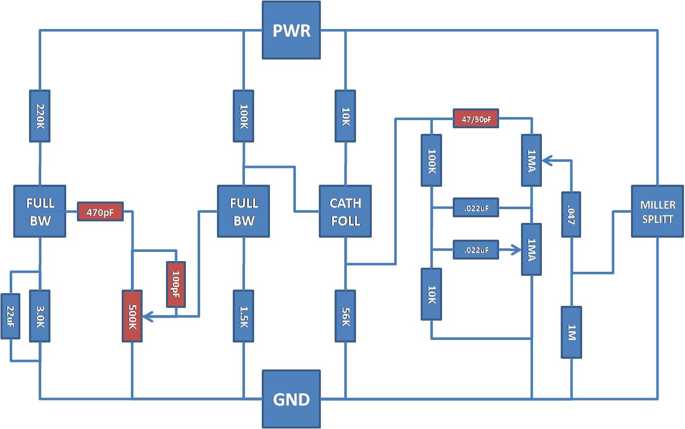
The preamp, for this particular amp is pretty darned ol' simple, really. The preamp, literally, consists of TWO stages, between which is a "Volume" or "Gain" control. I wasn't able to find any really well presented VOX AC30 schematics, so I took the liberty of doing a "block diagram" version and attaching it. It has all the relevant "stuff" included.
Stage 1 of the VOX AC30 is a relatively "stiff" and somewhat "low gain" stage, as can be seen from the 3.0K resistor in the cathode of the stage and the high value plate resistor (220K). This stage is bypassed with a 22uF capacitor, giving it pretty much flat gain response for the signals entering the stage. At the output of the stage is the first "interesting" element of this particular amp.
The plate is coupled to the 500K "Gain" control via a 470pF capacitor. This provides a shelving frequency of roughly 675Hz, just slighly lower than the Marshall interstage coupling created. Further to that, like the Marshall design, VOX put a 100pF capacitor from the top of the Gain control to the wiper of the gain control to further bypass high frequencies and provide additional brightness when the Gain is turned down - although the "reach" of this 270pF capacitor is significantly less than that of the much larger cap on the Marshall. This 675Hz high pass filter, coupled with the higher frequencies coupled into the second stage of the amp is the start for that "VOX Chime" that we're all so enamoured, or not, with.
The next stage, is a "warmer" and more "dynamic" stage with the more "standard" 1.5K cathode resistor and 100K plate resistor. This stage is not bypassed, by a capacitor in the cathode, so we have, a slighly lower gain stage that also exhibits a flat frequency response. This stage is coupled to a cathode follower which, then drives the tone stack.
This tone stack is interesting and it, like many other elements of the VOX AC30, has a lot of tube guru's providing all kinds of unique ideas of where it was derived from... there are several sites, in the internet, dedicated to showing how Gibson mis-drew the schematics for their GA-70 series of amplifiers showing the bass control incorrectly grounded. I've searched and, apart from the sites that say this was done, I've not been able to find the actual "incorrect" Gibson schematics. I've got books of them, here, and they're all Bandaxall (James) tone stacks, not the VOX tone stack. Whether or not this is a mistake is up for grabs and I don't really care to get into that part of the "arguement". Fact of the matter is, this tone stack contributes a great deal to the VOX tone... and whether it was a copy of a mistaken schematic some 50+ years ago is neither here, nor there, IMO. It is what it is, period.
There are elements from two different tone stacks, here. The first is the Bandaxall stack - and that covers, basically, how the bass section of this thing works. The Treble section was taken from Fender/Marshall designs of the day and, together, they create the relatively "unique" VOX tone stack. There are dozens of ways to draw/re-draw this, so, take your pick.
Here's generally how this thing works: The signal enters at the junction of the 47pF capacitor and the 100K resistor. That 100K resistor acts, in this stack, as in the Fender/Marshall stacks as a "slope" resistor generally setting the balance of high and low frequency ranges with an "upward slope" in favor of the treble frequencies. No wonder, really, as VOX was getting the same complaints as Fender was, the guitar was getting "lost" in the mix, and they needed it to "stand out" - hence the higher value slope resistor, deemphasizing the bass out of the stack.
The 47pF capacitor (Treble) is TINY compared to the much larger 250pF cap used on Fenders and the even larger version on Marshalls (470pF). This capacitor effectively blocks pretty much but all of the highest "glassy" and "chimy" frequencies and only lets them through. The other thing, here, is the size of the "Treble" control - 1,000,000 ohms, on the VOX, versus roughly 250,000 ohms on the Fender / Marshall stacks. This creates an additional "slope" giving significantly more precedence to the treble, than in the Fender and Marshall stack when it's turned anywhere past about 1/3 to 1/2 the way "up".
The "Bass / Mid" section is interesting, here, as well. Those frequencies drop out of the bottom of the 100K resistor. The top .022uF capacitor couples it all to the top of the 1M Bass control. In this case, different from the Fender/Marshall, the shelf frequency for this high pass filter is fixed as the Bass control is not setup like a variable resistor, but a true pot. The shelf, here, is quite low, in the 7.5Hz region. which means the entire frequency range, here, is fed up through the bottom of the Treble control.
The second, or bottom, .022uF capacitor, is connected to the wiper of the Bass Control. This forms a "low pass" network whose shelf changes as the wiper of the Bass control is moved. This "blocks" the low frequencies from passing through the control, to ground. The high frequencies, however, will pass through the capacitor, through the wiper of the pot and to ground. This, low pass filter, coupled with the high pass filter formed by the 47pF capacitor and the Treble/Bass controls creates a "mid-cut" the depth/frequency of which changes as the Bass control wiper is varied.
In the end, two things, in this amp, contribute SIGNIFICANTLY to the development of the VOX AC30 sound. The first, is the 675Hz high pass filter coupling stage 1 to stage 2, combined with the 100pF capacitor across the "Gain" control. The second important element in the development of the AC30 sound is the tone stack, of which there are three significant differences that contribute to that AC30 tone - the first is the 47pF capacitor forming the high pass network for the Treble side of the stack. This couples only the "chimy" frequencies across and the "reach" of which is not as deep as either the Fender or the Marshall.
The second notable factor, here, is that the "slope" of this stack is quite high, due to the higher value of the slope resistor (100K) AND the higher value of Treble (1M)control. This significantly "skews" the frequency response of this amp toward the higher, more "chimy" frequency range.
The final "noteable" factor, here is the design of the bass control and "mid-cut" section. The bottom .022uF capacitor will "bleed" off high frequencies to ground and block the low frequencies pushing them "back through the top .022uF capacitor and the "Bass" control. The Bass cut occurs when the Bass control wiper is at the top of the control and the "pass through", or "boost" (incorrect term but I have to describe it some way) occurs when the wiper is at the bottom of the bass control.
That about covers the VOX AC30 Preamp... 675Hz shelf... a tone stack in favor of treble frequencies... and there you have it.
Dar
The preamp, for this particular amp is pretty darned ol' simple, really. The preamp, literally, consists of TWO stages, between which is a "Volume" or "Gain" control. I wasn't able to find any really well presented VOX AC30 schematics, so I took the liberty of doing a "block diagram" version and attaching it. It has all the relevant "stuff" included.
Stage 1 of the VOX AC30 is a relatively "stiff" and somewhat "low gain" stage, as can be seen from the 3.0K resistor in the cathode of the stage and the high value plate resistor (220K). This stage is bypassed with a 22uF capacitor, giving it pretty much flat gain response for the signals entering the stage. At the output of the stage is the first "interesting" element of this particular amp.
The plate is coupled to the 500K "Gain" control via a 470pF capacitor. This provides a shelving frequency of roughly 675Hz, just slighly lower than the Marshall interstage coupling created. Further to that, like the Marshall design, VOX put a 100pF capacitor from the top of the Gain control to the wiper of the gain control to further bypass high frequencies and provide additional brightness when the Gain is turned down - although the "reach" of this 270pF capacitor is significantly less than that of the much larger cap on the Marshall. This 675Hz high pass filter, coupled with the higher frequencies coupled into the second stage of the amp is the start for that "VOX Chime" that we're all so enamoured, or not, with.
The next stage, is a "warmer" and more "dynamic" stage with the more "standard" 1.5K cathode resistor and 100K plate resistor. This stage is not bypassed, by a capacitor in the cathode, so we have, a slighly lower gain stage that also exhibits a flat frequency response. This stage is coupled to a cathode follower which, then drives the tone stack.
This tone stack is interesting and it, like many other elements of the VOX AC30, has a lot of tube guru's providing all kinds of unique ideas of where it was derived from... there are several sites, in the internet, dedicated to showing how Gibson mis-drew the schematics for their GA-70 series of amplifiers showing the bass control incorrectly grounded. I've searched and, apart from the sites that say this was done, I've not been able to find the actual "incorrect" Gibson schematics. I've got books of them, here, and they're all Bandaxall (James) tone stacks, not the VOX tone stack. Whether or not this is a mistake is up for grabs and I don't really care to get into that part of the "arguement". Fact of the matter is, this tone stack contributes a great deal to the VOX tone... and whether it was a copy of a mistaken schematic some 50+ years ago is neither here, nor there, IMO. It is what it is, period.
There are elements from two different tone stacks, here. The first is the Bandaxall stack - and that covers, basically, how the bass section of this thing works. The Treble section was taken from Fender/Marshall designs of the day and, together, they create the relatively "unique" VOX tone stack. There are dozens of ways to draw/re-draw this, so, take your pick.
Here's generally how this thing works: The signal enters at the junction of the 47pF capacitor and the 100K resistor. That 100K resistor acts, in this stack, as in the Fender/Marshall stacks as a "slope" resistor generally setting the balance of high and low frequency ranges with an "upward slope" in favor of the treble frequencies. No wonder, really, as VOX was getting the same complaints as Fender was, the guitar was getting "lost" in the mix, and they needed it to "stand out" - hence the higher value slope resistor, deemphasizing the bass out of the stack.
The 47pF capacitor (Treble) is TINY compared to the much larger 250pF cap used on Fenders and the even larger version on Marshalls (470pF). This capacitor effectively blocks pretty much but all of the highest "glassy" and "chimy" frequencies and only lets them through. The other thing, here, is the size of the "Treble" control - 1,000,000 ohms, on the VOX, versus roughly 250,000 ohms on the Fender / Marshall stacks. This creates an additional "slope" giving significantly more precedence to the treble, than in the Fender and Marshall stack when it's turned anywhere past about 1/3 to 1/2 the way "up".
The "Bass / Mid" section is interesting, here, as well. Those frequencies drop out of the bottom of the 100K resistor. The top .022uF capacitor couples it all to the top of the 1M Bass control. In this case, different from the Fender/Marshall, the shelf frequency for this high pass filter is fixed as the Bass control is not setup like a variable resistor, but a true pot. The shelf, here, is quite low, in the 7.5Hz region. which means the entire frequency range, here, is fed up through the bottom of the Treble control.
The second, or bottom, .022uF capacitor, is connected to the wiper of the Bass Control. This forms a "low pass" network whose shelf changes as the wiper of the Bass control is moved. This "blocks" the low frequencies from passing through the control, to ground. The high frequencies, however, will pass through the capacitor, through the wiper of the pot and to ground. This, low pass filter, coupled with the high pass filter formed by the 47pF capacitor and the Treble/Bass controls creates a "mid-cut" the depth/frequency of which changes as the Bass control wiper is varied.
In the end, two things, in this amp, contribute SIGNIFICANTLY to the development of the VOX AC30 sound. The first, is the 675Hz high pass filter coupling stage 1 to stage 2, combined with the 100pF capacitor across the "Gain" control. The second important element in the development of the AC30 sound is the tone stack, of which there are three significant differences that contribute to that AC30 tone - the first is the 47pF capacitor forming the high pass network for the Treble side of the stack. This couples only the "chimy" frequencies across and the "reach" of which is not as deep as either the Fender or the Marshall.
The second notable factor, here, is that the "slope" of this stack is quite high, due to the higher value of the slope resistor (100K) AND the higher value of Treble (1M)control. This significantly "skews" the frequency response of this amp toward the higher, more "chimy" frequency range.
The final "noteable" factor, here is the design of the bass control and "mid-cut" section. The bottom .022uF capacitor will "bleed" off high frequencies to ground and block the low frequencies pushing them "back through the top .022uF capacitor and the "Bass" control. The Bass cut occurs when the Bass control wiper is at the top of the control and the "pass through", or "boost" (incorrect term but I have to describe it some way) occurs when the wiper is at the bottom of the bass control.
That about covers the VOX AC30 Preamp... 675Hz shelf... a tone stack in favor of treble frequencies... and there you have it.
Dar