#1 · Aug 13, 2008 22:22 UTC
So, my thought is, start with the guy that sort of "started it all" - Leo Fender. Fenders are known for one thing - CLEAN! You don't see many death metal bands sporting Fender Twin stacks these days and there's a reason for that. Leo focused on three things: 1) Quality products, 2) Competitive pricing and 3) Amplifying cleanly. Because of this basic focus, the Fender circuits are derived straight from the RCA Tube Manuals.
Back in the day, in order to sell tubes, tube companies would produce splendid books that not only told customers how great the tubes were but actually had suggested circuits for various applications that maximized whatever quality of whatever tube it was they were trying to sell. Rather than spend a lot of time in R&D, Leo Fender took these already "cooked" designs and put them together into tube amps that made history. He did a great job and I'm not trying to belittle him, at all. Leo used his resources incredibly wisely and, as a result, created a highly successful company in the process.
What we ended up with, as a result of his personal approach is a "hi-fi" tube amp. Early designs, such as the Fender Champ, really didn't have much to them. Two gain stages and a power amp with a single output tube running in class A. Early Champs consisted of a single 12AX7, or similar, preamp tube and a volume control. That was it. Later Champs added a tone control, which was simply a "high cut". Later Champs got even more elaborate with Bass / Treble controls (fixed midrange) and finally vibrato/tremolo. Of course, Fender followed his customers and, eventually, they were wanting louder amps. It's hard to get "loud" with a pure Class A (single ended (SE) output) so Leo did what every good designer would and grabbed a Class AB output (push-pull) which significantly increased the power output... but I digress.
Fender Preamp Stage Voicing
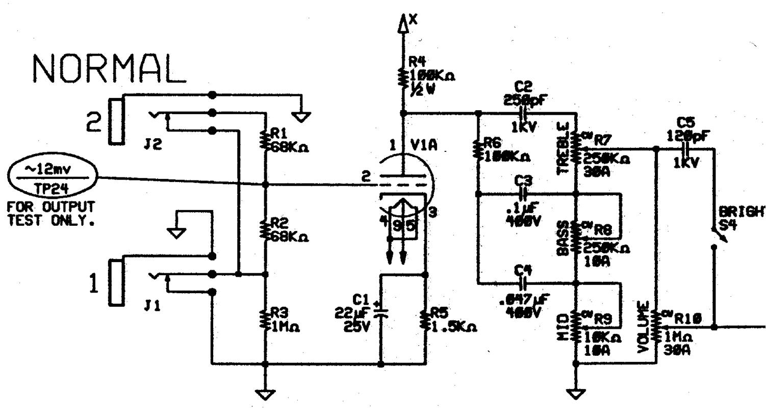
Attached is a JPG of the first stage of a normal Fender Preamp. This one happens to be from the Twin Reissue. Doesn't matter, almost all Fender amps follow this EXACT same topology. Remember I said, above, that Leo Fender took designs straight from the RCA Tube Manual and that his focus was on "purity", in terms of amplification.
Well, in a Fender amp ALL stages amplify all frequencies equally - flat response is what this is called? So, if I'm looking at a schematic, how do I tell? If you look at this JPG file, you'll see the cathode resistor, on the tube (R5 - approximately bottom center). This resistor "biases" the tube and sets its operating point. It also determines how much "gain" the tube stage will have and how "warm" or "cold" or "harsh" it will be. The basic rule of thumb, here is: 1.5K values, in this position, are the balance between "warm" and "cold/harsh". The lower the resistor value the "warmer" the tube stage will sound. The larger this resistor value the "dryer" or "harsher" this stage will sound. This resistor actually allows, or disallows more current to flow through the tube. A larger value, here, reduces/disallows current flow. A lower value in this position allows more current to flow. Greater current = warmer.
Immediately we jump to the conclusion that no resistor at all would be THE WARMEST! Well, in truth, it is BUT!!!! always a but. When this resistor is missing, tube gain, or transconductance, is at its highest level. Transconductance is a term used to describe how "efficient" a tube is at converting small input signals into huge output signals. The input signal will need to be almost nothing (roughly 1 / 1000 of what a guitar would put out) in order for this stage to even run without all out maddening distortion. So, in practice, there needs to be some value of resistance, here. Typical values, in this spot, range from 820 ohms to roughly 3000 (3k) ohms. Most Marshalls have at least one 820 ohm resistor in one of their stages.
Fenders, typically, utilize 1.5K ohm resistors in this spot. Now, moving on to other things. If you'll notice, to the left of R5 is C1 (22uF, 25V). This is what is called a capacitor. I know... I know... the size of this capacitor actually determines the frequency response of this stage. There is a formula:
(1 / 2 * pi * R * C)
Where:
pi = 3.1415
R = Resistance value in ohms
C = Capacitor value in farads
The result of this math is a "cutoff frequency". This frequency acts as a high pass filter which operates at 6dB per octave. So, for every octave below the "cutoff" frequency, the level will be 6dB less.
For this amp, this stage passes all frequencies above 4.8Hz (well below 20Hz and the threshold of human hearing) with flat response. Very clean.
This cathode bypass capacitor has another effect on the tube operation. It increases SIGNAL gain and makes this stage operate, when signals are present, more like it would if there were no cathode resistor at all. The DC levels, which control how much current flows all the time when no signal is present, doesn't change, at all.
Finally, the input resistor (R3, 1M) is what is used to "capture" your guitar signal. The larger the value of this resistor the more "cleanly" the preamp stage will pick up the guitar signal AND all of its minute variations and harmonics. In a Fender-style preamp this value is, typically 1M. A high value resistor, like this, will not "load" your guitar pickups. As this value creeps downward (500K, 100K, 68K, etc) the input, to the preamp, will gradually "load" your guitars pickups. The greater the "load" presented by the input impedance, to the preamp, the "duller" your guitar will actually sound. At some point, just below the 100K mark, it starts to get harder and harder to differentiate between the sound of a Strat or a Les Paul being plugged into the amplifier, believe it or not. That's why you rarely see a value, in this position, below 100K ohms.
The other resistor, there, (68K) is a "grid stop" resistor. It's sole function is to "protect" the tube from any electricity that might be coming into the input (from poorly designed effects units, etc.) from damaging the tube. You will see this type of "protection" in solid-state effects pedals, as well, feeding the input transistors or op-amps.
You'll notice, here, that immediately following the first gain stage is the tone stack. The tone stack, on this amp, consists of 3 capacitors (C2/250pF, C3/.1uF and C4/.047uF), 1 resistor (R6/100K) and 3 potentiometers/variable resistors (R7/250K, R8/250K, R9/10k). This comprises the "tone stack" for this amplifier. C2/250pF is the "treble cap" and determines, in part, the "balance" of high frequencies to low frequencies in the tone stack. The resistor (R6/100K) is what is commonly referred to as the "slope resistor" and this resistor controls the balance of high frequencies to low frequencies. The larger this value the more dominant the high frequencies will be. The lower this value, the less dominant they will be. Marshall uses 33K in this position (more low frequency) and Fender uses 100K for that more "glassy" high end they're famous for.
One final note, if you don't see a capacitor across the cathode resistor (i.e. if C1 were non-existant) this means that the stage has a ruler flat frequency response from 0Hz (DC) to the frequency limit of the tube. These are also common in Fenders.
Back in the day, in order to sell tubes, tube companies would produce splendid books that not only told customers how great the tubes were but actually had suggested circuits for various applications that maximized whatever quality of whatever tube it was they were trying to sell. Rather than spend a lot of time in R&D, Leo Fender took these already "cooked" designs and put them together into tube amps that made history. He did a great job and I'm not trying to belittle him, at all. Leo used his resources incredibly wisely and, as a result, created a highly successful company in the process.
What we ended up with, as a result of his personal approach is a "hi-fi" tube amp. Early designs, such as the Fender Champ, really didn't have much to them. Two gain stages and a power amp with a single output tube running in class A. Early Champs consisted of a single 12AX7, or similar, preamp tube and a volume control. That was it. Later Champs added a tone control, which was simply a "high cut". Later Champs got even more elaborate with Bass / Treble controls (fixed midrange) and finally vibrato/tremolo. Of course, Fender followed his customers and, eventually, they were wanting louder amps. It's hard to get "loud" with a pure Class A (single ended (SE) output) so Leo did what every good designer would and grabbed a Class AB output (push-pull) which significantly increased the power output... but I digress.
Fender Preamp Stage Voicing
Attached is a JPG of the first stage of a normal Fender Preamp. This one happens to be from the Twin Reissue. Doesn't matter, almost all Fender amps follow this EXACT same topology. Remember I said, above, that Leo Fender took designs straight from the RCA Tube Manual and that his focus was on "purity", in terms of amplification.
Well, in a Fender amp ALL stages amplify all frequencies equally - flat response is what this is called? So, if I'm looking at a schematic, how do I tell? If you look at this JPG file, you'll see the cathode resistor, on the tube (R5 - approximately bottom center). This resistor "biases" the tube and sets its operating point. It also determines how much "gain" the tube stage will have and how "warm" or "cold" or "harsh" it will be. The basic rule of thumb, here is: 1.5K values, in this position, are the balance between "warm" and "cold/harsh". The lower the resistor value the "warmer" the tube stage will sound. The larger this resistor value the "dryer" or "harsher" this stage will sound. This resistor actually allows, or disallows more current to flow through the tube. A larger value, here, reduces/disallows current flow. A lower value in this position allows more current to flow. Greater current = warmer.
Immediately we jump to the conclusion that no resistor at all would be THE WARMEST! Well, in truth, it is BUT!!!! always a but. When this resistor is missing, tube gain, or transconductance, is at its highest level. Transconductance is a term used to describe how "efficient" a tube is at converting small input signals into huge output signals. The input signal will need to be almost nothing (roughly 1 / 1000 of what a guitar would put out) in order for this stage to even run without all out maddening distortion. So, in practice, there needs to be some value of resistance, here. Typical values, in this spot, range from 820 ohms to roughly 3000 (3k) ohms. Most Marshalls have at least one 820 ohm resistor in one of their stages.
Fenders, typically, utilize 1.5K ohm resistors in this spot. Now, moving on to other things. If you'll notice, to the left of R5 is C1 (22uF, 25V). This is what is called a capacitor. I know... I know... the size of this capacitor actually determines the frequency response of this stage. There is a formula:
(1 / 2 * pi * R * C)
Where:
pi = 3.1415
R = Resistance value in ohms
C = Capacitor value in farads
The result of this math is a "cutoff frequency". This frequency acts as a high pass filter which operates at 6dB per octave. So, for every octave below the "cutoff" frequency, the level will be 6dB less.
For this amp, this stage passes all frequencies above 4.8Hz (well below 20Hz and the threshold of human hearing) with flat response. Very clean.
This cathode bypass capacitor has another effect on the tube operation. It increases SIGNAL gain and makes this stage operate, when signals are present, more like it would if there were no cathode resistor at all. The DC levels, which control how much current flows all the time when no signal is present, doesn't change, at all.
Finally, the input resistor (R3, 1M) is what is used to "capture" your guitar signal. The larger the value of this resistor the more "cleanly" the preamp stage will pick up the guitar signal AND all of its minute variations and harmonics. In a Fender-style preamp this value is, typically 1M. A high value resistor, like this, will not "load" your guitar pickups. As this value creeps downward (500K, 100K, 68K, etc) the input, to the preamp, will gradually "load" your guitars pickups. The greater the "load" presented by the input impedance, to the preamp, the "duller" your guitar will actually sound. At some point, just below the 100K mark, it starts to get harder and harder to differentiate between the sound of a Strat or a Les Paul being plugged into the amplifier, believe it or not. That's why you rarely see a value, in this position, below 100K ohms.
The other resistor, there, (68K) is a "grid stop" resistor. It's sole function is to "protect" the tube from any electricity that might be coming into the input (from poorly designed effects units, etc.) from damaging the tube. You will see this type of "protection" in solid-state effects pedals, as well, feeding the input transistors or op-amps.
You'll notice, here, that immediately following the first gain stage is the tone stack. The tone stack, on this amp, consists of 3 capacitors (C2/250pF, C3/.1uF and C4/.047uF), 1 resistor (R6/100K) and 3 potentiometers/variable resistors (R7/250K, R8/250K, R9/10k). This comprises the "tone stack" for this amplifier. C2/250pF is the "treble cap" and determines, in part, the "balance" of high frequencies to low frequencies in the tone stack. The resistor (R6/100K) is what is commonly referred to as the "slope resistor" and this resistor controls the balance of high frequencies to low frequencies. The larger this value the more dominant the high frequencies will be. The lower this value, the less dominant they will be. Marshall uses 33K in this position (more low frequency) and Fender uses 100K for that more "glassy" high end they're famous for.
One final note, if you don't see a capacitor across the cathode resistor (i.e. if C1 were non-existant) this means that the stage has a ruler flat frequency response from 0Hz (DC) to the frequency limit of the tube. These are also common in Fenders.