#1 · Aug 15, 2008 20:46 UTC
It's no secret that the first amp brought into the limelight, created by Jim Marshall, was a copy of the Fender Bassman, specifically the 5F6-A chassis. There are some interesting, and subtle, differences, but we'll save that comparison for a later time. Let's just take a quick look at what Marshall has to offer. When the first JTM45's were released Jim/Ken were futzing around with component values so there are a lot of versions of this thing, most of which no one really talks about. What they ended up with, though, after a bit of work, is a topology that really didn't change much, ever! The circuit in the JTM45 ended up in the JCM800, the JCM900, JCM9000, etc. Rather than change a lot of stuff in the basic design, they just added features and renamed the amps.
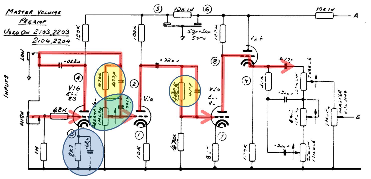
I'm going to spend most of my time on the JCM800, chassis 2203/4 just cuz it's my favorite... actually, for another reason, it's got ALL the Marshall "stuff" in it. Here's a link with the Marshall "standard preamp" design. I have included a color-coded version of the Master Volume preamp, here, for review.
http://www.drtube.com/schematics/marshall/jcm800pr.gif
So, onward, let's dig through this thing. The standard Marshall preamp has two inputs a "High" and a "Low" input. The "high" input adds two things: 1) An extra gain stage and 2) A "high pass" filter... so "higher gain" and fewer low frequencies. I'm going to focus on the "High" input as this is "the sound of Marshall" that we're all used to. The other input, most folks don't use it, much.
So, plug the guitar into the "High" input and you see the 1M input impedance - as per the Fender. This will not load the guitar. The 68K grid-block resistor is there to protect the tube, as per Fender, too. This is standard design. Tube V1B is the first tube the signal hits when a guitar is plugged into the "High". This stage, in the Marshall, is a bit lower gain than the first stage in the Fender. WHAT???? In the Fender, the Cathode resistor was 1.5K ohms. Remember, we discussed, that the lower the value of the resistor, in this position, the smaller the signal has to be in order to get a large output and the higher current that is going through the tube. Higher current = "warmer". Lower current = "colder" or more "sterile" and "brittle". Interestingly Marshall starts out with a more "brittle" stage than the Fender amp does.
Another difference, in this stage is the fact that across that 2.7K resistor is a .68uF capacitor. This is a MUCH smaller value (36 times smaller) than the 25uF capacitor used in the Fender amp. Using the 1/(2 x pi x R x C) equation we find this circuit provides a high-pass filter with a shelf centered at 86Hz. This is the first difference between the Fender and the Marshall. In the Fender, stage 1 is flat response from 8Hz to 20kHz. In the Marshall we start the "flat" response at 86Hz.
The output of this stage is coupled through the .022uF capacitor (used ONLY for blocking the DC plate voltage from V1). The signal hits the next part of the Marshall equation which is the parallel combination of a 470K resistor and 470pF capacitor. These two components, together, form a frequency selective network which blocks pretty much everything below 720Hz (1 / 2 * pi * R * C.... 1/(2 * 3.1415 * 470000 * 470E-12 - where 470E-12 is 470 x 10 to the minus 12 power).
This is, essentially, a high pass filter, but it forms a slightly different slope than the standard high pass filter. Marshall describes this as a rising slope of 10dB per decade. A "decade" is a 10x multiplication in frequency. So, if the slope upward starts at 720Hz, at 7200Hz the output would be 10dB higher. This 720Hz shelf is THE "sound of Marshall". It's all right here, folks.
Let's view these two stages a little more closely. Unlike the Fender first stage, this Marshall stage has less gain and can take a MUCH larger input signal swing WITHOUT distortion than what the Fender's first stage can. WOW! So, NO distortion would occur in this stage, normally. The signal is then "filtered" or "shelved" at 86Hz by the feedback network connected to the cathode, it's then pushed to a SECOND filter (still clean) that shelves AGAIN at 720Hz. This is, then, "picked up" by the "Gain" control and fed into the second stage. Because the signal DID NOT pass through a tone stack, the input signal level, to this second stage will still be higher than the input signal level at the 2nd stage of a Fender amp!
OK... moving onward... V1a, second stage tube... if you notice there's a 10K resistor at the cathode of this stage and NO capacitor. This stage is FLAT frequency response AND lower gain. The input signal can, again, swing quite a bit without distortion, but at this stage some distortion will be generated here. Because of tube charactaristics there will be slightly more distortion on the negative direction of the signal (which WAS positive feeding the first stage - each stage "inverts" the signal 180 degrees) and less distortion generated on the positive direction of the signal. It's been filtered one time, already, at 86 and 720Hz and THEN the distortion starts getting generated. As per the first stage, this stage has an even HIGHER value resistor in the cathode position. This biases this stage even "colder" and, in reality, makes it sound even "thinner".
At the output of this stage, through another .022uF capacitor and ANOTHER 470K/470pF parallel circuit the signal will pass. AGAIN with the 720Hz filter. So the partially distorted signal, from the last stage, is fed through another 720Hz filter and the low end is, again, removed/filtered out. This feeds the third, and final GAIN stage in the preamp, V2a. This stage has a very low value resistor in the cathode portion (820 ohms). Again, there is no cathode bypass capacitor which means the stage gain, here, is flat. A couple of things, to note, here, too. First, the small resistor in the cathode position biases this stage "hot" and "warms up" the signal. Secondarily, the small value of resistor makes this stage EXTREMELY sensitive to input signal variations (small signals produce HUGE changes) and thus is significantly MUCH MORE PRONE to distorting than stages 1 and 2. The signal has been filtered at 720Hz twice, prior to this so it's pretty "clean" in the low frequency region.
Stage 3 is directly coupled to stage 4 which has no plate resistor and a 100K cathode resistor. Stage 4 is what is known as a "Cathode Follower". This stage has no gain. The input signal is "coupled" directly to the output. This stage is designed, primarily, to be an "impedance" converter, converting the high output impedance of the preceding stage to a low output impedance for this stage. This allows almost the ENTIRE signal, generated by the stage previous to this, to be "dropped", or "fed into" the tone stack. Secondarily, the tone stack is now part of the "feedback" portion of this tube stage, which affects the character of the tone stack, overall. I'm almost out of characters, so I need to quit this thread and head into the next one...
BRB!
Dar
I'm going to spend most of my time on the JCM800, chassis 2203/4 just cuz it's my favorite... actually, for another reason, it's got ALL the Marshall "stuff" in it. Here's a link with the Marshall "standard preamp" design. I have included a color-coded version of the Master Volume preamp, here, for review.
http://www.drtube.com/schematics/marshall/jcm800pr.gif
So, onward, let's dig through this thing. The standard Marshall preamp has two inputs a "High" and a "Low" input. The "high" input adds two things: 1) An extra gain stage and 2) A "high pass" filter... so "higher gain" and fewer low frequencies. I'm going to focus on the "High" input as this is "the sound of Marshall" that we're all used to. The other input, most folks don't use it, much.
So, plug the guitar into the "High" input and you see the 1M input impedance - as per the Fender. This will not load the guitar. The 68K grid-block resistor is there to protect the tube, as per Fender, too. This is standard design. Tube V1B is the first tube the signal hits when a guitar is plugged into the "High". This stage, in the Marshall, is a bit lower gain than the first stage in the Fender. WHAT???? In the Fender, the Cathode resistor was 1.5K ohms. Remember, we discussed, that the lower the value of the resistor, in this position, the smaller the signal has to be in order to get a large output and the higher current that is going through the tube. Higher current = "warmer". Lower current = "colder" or more "sterile" and "brittle". Interestingly Marshall starts out with a more "brittle" stage than the Fender amp does.
Another difference, in this stage is the fact that across that 2.7K resistor is a .68uF capacitor. This is a MUCH smaller value (36 times smaller) than the 25uF capacitor used in the Fender amp. Using the 1/(2 x pi x R x C) equation we find this circuit provides a high-pass filter with a shelf centered at 86Hz. This is the first difference between the Fender and the Marshall. In the Fender, stage 1 is flat response from 8Hz to 20kHz. In the Marshall we start the "flat" response at 86Hz.
The output of this stage is coupled through the .022uF capacitor (used ONLY for blocking the DC plate voltage from V1). The signal hits the next part of the Marshall equation which is the parallel combination of a 470K resistor and 470pF capacitor. These two components, together, form a frequency selective network which blocks pretty much everything below 720Hz (1 / 2 * pi * R * C.... 1/(2 * 3.1415 * 470000 * 470E-12 - where 470E-12 is 470 x 10 to the minus 12 power).
This is, essentially, a high pass filter, but it forms a slightly different slope than the standard high pass filter. Marshall describes this as a rising slope of 10dB per decade. A "decade" is a 10x multiplication in frequency. So, if the slope upward starts at 720Hz, at 7200Hz the output would be 10dB higher. This 720Hz shelf is THE "sound of Marshall". It's all right here, folks.
Let's view these two stages a little more closely. Unlike the Fender first stage, this Marshall stage has less gain and can take a MUCH larger input signal swing WITHOUT distortion than what the Fender's first stage can. WOW! So, NO distortion would occur in this stage, normally. The signal is then "filtered" or "shelved" at 86Hz by the feedback network connected to the cathode, it's then pushed to a SECOND filter (still clean) that shelves AGAIN at 720Hz. This is, then, "picked up" by the "Gain" control and fed into the second stage. Because the signal DID NOT pass through a tone stack, the input signal level, to this second stage will still be higher than the input signal level at the 2nd stage of a Fender amp!
OK... moving onward... V1a, second stage tube... if you notice there's a 10K resistor at the cathode of this stage and NO capacitor. This stage is FLAT frequency response AND lower gain. The input signal can, again, swing quite a bit without distortion, but at this stage some distortion will be generated here. Because of tube charactaristics there will be slightly more distortion on the negative direction of the signal (which WAS positive feeding the first stage - each stage "inverts" the signal 180 degrees) and less distortion generated on the positive direction of the signal. It's been filtered one time, already, at 86 and 720Hz and THEN the distortion starts getting generated. As per the first stage, this stage has an even HIGHER value resistor in the cathode position. This biases this stage even "colder" and, in reality, makes it sound even "thinner".
At the output of this stage, through another .022uF capacitor and ANOTHER 470K/470pF parallel circuit the signal will pass. AGAIN with the 720Hz filter. So the partially distorted signal, from the last stage, is fed through another 720Hz filter and the low end is, again, removed/filtered out. This feeds the third, and final GAIN stage in the preamp, V2a. This stage has a very low value resistor in the cathode portion (820 ohms). Again, there is no cathode bypass capacitor which means the stage gain, here, is flat. A couple of things, to note, here, too. First, the small resistor in the cathode position biases this stage "hot" and "warms up" the signal. Secondarily, the small value of resistor makes this stage EXTREMELY sensitive to input signal variations (small signals produce HUGE changes) and thus is significantly MUCH MORE PRONE to distorting than stages 1 and 2. The signal has been filtered at 720Hz twice, prior to this so it's pretty "clean" in the low frequency region.
Stage 3 is directly coupled to stage 4 which has no plate resistor and a 100K cathode resistor. Stage 4 is what is known as a "Cathode Follower". This stage has no gain. The input signal is "coupled" directly to the output. This stage is designed, primarily, to be an "impedance" converter, converting the high output impedance of the preceding stage to a low output impedance for this stage. This allows almost the ENTIRE signal, generated by the stage previous to this, to be "dropped", or "fed into" the tone stack. Secondarily, the tone stack is now part of the "feedback" portion of this tube stage, which affects the character of the tone stack, overall. I'm almost out of characters, so I need to quit this thread and head into the next one...
BRB!
Dar