23 posts
This is going to be a series of posts centered around Fenders Hot Rod Deluxe (HRD) amp. Why the HRD? Because the schematics are available from here
http://www.fender.com/support/amp_schematics/pdfs/Hot_Rod_Deluxe_Schematic.pdf
and provided by Fender, which makes this much more "legal" that some amps. Plus, the HRD incorporates so many things that we've talked about in a single amp. It's just a nice platform for discussion. There are mods that can be made, to this amp, that will significantly change it. There are things that Fender has done, in the topology, which can be nicely adapted to other amps.
I'm going to also use this particular platform to discuss ideas of voltage, current, resistance, reactance and power. I think it makes sense to do these things in the context of a real amp. This will also get us into reading schematics a bit more, too. So, all-in-all, it's a good thing. I'll talk about modding the amp, PCB work, as much as I think to, etc.
Have fun, enjoy. There'll be a lot of sub-posts, in here, as I'll be putting everything in this single topic.
Dar
The part I like about the Fender schematics is the fact that they post both AC and DC voltages. That way, you can apply your tube knowledge to the circuit and actually see measured voltages at each part. You can see the effects of interstage attenuators, stage gain, etc. Its a great way to enhance your learning, and skills.
So, lets get right to it and take a look at this particular amp. While Im going along, here, Im going to be explaining things like series circuits, parallel circuits, current, voltage, power and signal division or splitting so that we can view the effects of various elements on the final outcome of the amp.
The first thing I take a look at, when I grab a schematic like this, are the notes. Fender has these, in this diagram, on the lower right. It tells how the voltages were derived in the schematic, what wattage the resistors are, what voltage ratings are on the capacitors, all kinds of neat information that youre going to need if you end up servicing and/or modifying this amp. Bias adjustment procedures are there, as well
The Power Supply Part 2
We left off as the inductor was filtering out some RFI generated by the conversion of AC into DC
One note, to add, here, is that you can also help to reduce noise/RFI, generated in the power supply, by bypassing each of the high value electrolytic capacitors with a high quality film capacitor (I typically use .01uF for this). That will help increase the high frequency range of the capacitors and help further bleed the noise. This is a common practice in digital/RF design and it works very well, here, too.
Dar
HRD First Preamp Stage Analysis
Lets get on with it. We saw, in the previous two posts, the power supply and its inner workings. Now, were moving on, to the first preamp stage photo attached. This stage is comprised of a single 12AX7A section.
As we saw, in the section on biasing tubes using load lines, the 100K plate resistor (R4) coupled with the 1.5K cathode resistor (R5) biases this tube, for DC, in the dead-center of the operational range. We also know that the larger the cathode resistor value, the colder the stage runs and the more brittle it sounds. The smaller the cathode resistor value the hotter the stage runs and the warmer it sounds. Fender chose a value thats pretty much smack in the middle of these two extremes which, well, would account for the clarity and the warmth you get when you buy a Fender amp. Its part of their trademark tone.
Two inputs to this amp, J1 and J2. Both feed through a 68K grid stopper resistor. These are standard issue, especially on vintage tube amps, to basically block any grid current from flowing, ever. That stops tube damage. With a guitar, thats probably not going to happen. However, with high signal levels, it could happen. With the 68K resistor in place, never going ot happen unless you plug the input into a wall socket, at which point you SHOULD destroy tubes! RadioTron Designers handbook specifies this value at 10K. Guitar amp folks just made it higher, period.
Inputs 1 and 2 are the same, on this amp. If youll notice both tips (pin 2 on each jack) feed into the 68K resistor. Both resistors meet in the same place acting as a mixer circuit for the two inputs. On many amps, the high gain input bypasses one of these two resistors, while the low-gain input actually connects them in series.
R3 is the input impedance and is the much used 1M value. This provides the least amount of loading to the guitar. 470K is another popular value, as weve seen, through the analysis of the JSX and the Sovtek amps. Fender typically uses 1M. A smaller value here will sound slightly darker than the 1M BUT produce less hiss through the amp. Its a tradeoff.
C1 (47uF) completely bypasses the 1.5K resistor at all audio frequencies. Theres another benefit here, that we havent discussed much. The cathode resistor, by itself, sets the DC operating point of the tube (how much current can flow, maximum, between the plate and the cathode) and that sets the sound of the stage (brittle to warm).
The plate resistor controls some of this, as well. First, the plate resistor sets the gain of the stage. The larger the value of plate resistor (typical is 100K, but 220K is also common) the more gain the stage will produce. A drawback, here, is the fact that the plate resistor also bounds, or limits, the plate current. A larger value of resistor, in this place, while allowing much more voltage gain, will also severely limit the current through the tube thus making it brittle, too, despite a smaller value cathode resistor. They both play a role, here. If youre looking to get maximum voltage gain, at this stage, and will warm up the sound a bit later in the amp, you can increase the plate resistor to, say, 220K and get a bit more gain out of the stage. Not a lot, but more.
So, thats how these two resistors interact. If you leave the cathode resistor unbypassed, the resistor creates what it is called negative feedback for the tube when the signal is presented. This reduces the overall gain of the stage quite a bit BUT, it makes the stage much more linear and much less prone to distortion. It tracks the signal in a much more clean and clear way.
If youre going for the maximum gain allowed by the plate resistor, then placing a capacitor across the cathode resistor will allow for this. The stage becomes somewhat non-linear as there is no negative feedback to bound the output gain, or cancel the distortion. 2nd harmonic distortion, in this case, reigns and thats pleasing for the guitarist. When the cathode is unbypassed, odd-harmonics are dominant (EVEN harmonics, including the second are still present) and those are more brittle and cold and buzzy.
The larger the capacitor the greater the gain. This capacitor can also be used for frequency selection, meaning I can change the frequency response of the stage. To determine the frequency response you will use the formula: 1 / (2 * pi * R * C) where pi = 3.1415, R = Cathode Resistor value and C = cathode bypass capacitor value.
Lets say, I want the stage to shelve at 97Hz, and a 1.5K resistor is already there. What capacitor to use? Wed use the formula 1 / (2 * pi * F * R), where F is the frequency we want to use. The result would be 1.09uF. 1uF is the standard value cap, so Id use that and deal with the slight variation from perfect. See how easy that was? You can use this little tool to do anything youd like with this.
The output of this stage is coupled from the plate to both the Drive and the Volume controls. On this amp Drive is the overdrive channel and Volume represents the Clean channel. You can see that there is a relay (K1A) that switches between these two channels. Theres a switching circuit we havent discussed, yet. There are, typically, two types of contacts in a relay: N.O. and N.C. The former refers to Normally Open (meaning switch is open) and the latter refers to Normally Closed (meaning the switch is close). This amp defaults to the Clean channel, as this relay clearly shows. The NC contacts are linked to the Volume control (pin 6).
So, lets take a look at a few things, here, with regards to the output. First the Drive section. Youll notice the Drive control is a series circuit comprised of C23 (1.5nF), R52 (180K) and the Drive pot (250K). C23 performs two functions: 1) Blocks the 225+ volts of DC voltage, on the plate, from getting into the next part of the circuit. Capacitors are often used for DC blocking as a primary function. 2) It forms a high pass filter with R52 (180K) and R7 (Drive 250K). The frequency of this filter is derived by using 1/(2*pi*R*C), where R, in this case, is the series combination of the Drive Control and R52. This produces a high pass filter of about 245Hz, if you do the math. If the amp just shelved at this point, it would have a lot of girth in the distortion.
Thats it for characters, here
This is great stuff, I don't "get" much of it but I do like my HRD a bunch.
HRD First Stage Preamp Part 2
So, there are a few electronics lessons to be learned, here. Lets take a look at what they area and how we can apply some things.
The combination of capacitor C23, R52 and R7 (DRIVE) form what is called a series circuit. Series circuits have an applied voltage on one end, with the signal/voltage having to travel through each, individual component (top-to-bottom) in this case. Because each component has a different resistance to the signal, or voltage, each component will drop or absorb some of the voltage. Because the voltage is applied across all components, in series, the flow of current, in each, will be equal.
In many guitar circuits, the series circuit produces what is commonly referred to as the voltage divider. The main job of the voltage divider is, well, to divide, or split, voltage. In this case, Fender knew that sending the entire signal, generated by the first tube in the amp, to the second stage would cause far too much distortion through the entire preamp. So, they created a voltage divider which significantly reduces the amount of signal which can pass from stage 1 to stage 2.
For a moment, lets pretend that C23 is shorted (0 resistance) and that R52 and R7 are both the same value (250K). When I apply the signal voltage to the top of C23, it will be distributed equally across R52 and R7 splitting it in exactly half (6dB of reduction). If the DRIVE control (R7) were larger, the signal would be distributed with a greater portion of it going to the DRIVE control and a lesser portion of it being dropped across R52. With C23 in the picture, the voltage drop is frequency dependant, meaning that at lower frequencies more of the signal will be dropped across the capacitor (essentially partially blocked) and less across the DRIVE control and R52. At higher frequencies the ratio changes.
The formula for the amount of voltage (percentage) dropped across the DRIVE control is:
250,000 / (Xc + 180,000 + 250,000). Xc is frequency dependant and derived from 1 / (2 * pi * F * 1.5e-9), where F = frequency in question. The X, typically, stands for reactance.
The signal is FURTHER divided by the potentiometer (DRIVE). When the wiper of the control is all the way at the top ALL of the signal voltage across the DRIVE control will be fed into the next stage. However, when the wiper moves toward the bottom of the DRIVE control a smaller and smaller portion of the signal will be fed into the next stage. As can be seen, here, the series circuit acts as a voltage divider.
Now, theres another way to revoice this stage and thats to add a resistor in parallel with C23. Thats how Marshall does it. They put a 470K resistor in parallel with a 470pF capacitor, for their voicing at 720Hz. This can be done, here, by removing this cap and replacing with another value and adding a resistor in series across it. Typically, if Im going to add a resistor in series, Ill solder the new cap in, or leave the old one, and then just tack the correct resistor to the underside of the PCB, soldering it to the individual pins of the cap. That works pretty well and Ive had no issues with that.
So, what can we change, here, in the first stage? We can change the cathode bypass capacitor to make the stage more frequency specific (Marshall uses the .68uF capacitor in this space for an 86Hz filter), or we can leave it at this high value for greater output/gain.
We were just discussing the high pass filter feeding the Drive control, being shelved at about 245Hz. We can increase this value to, say, 720Hz by changing C23. That can be done by using a 150nF capacitor (.15uF). That would create more sparkle and a more Marshall-esque voicing in this amp. Or, not
The final element, to consider, in the consideration of the HRD's first preamp stage is the "CLEAN channel". The CLEAN section of this preamp stage is pretty simple, and basic. As per the "DRIVE" section there is a voltage divider comprised of C18 (.022uF), R9 (220K) and R6 (250K). The 1/(2*pi*R*C) determines the cutoff frequency, here. This circuit is relatively flat response from 15Hz, and above. The .022uF capacitor is 15x larger than the 1.5nF capacitor in the "DRIVE" section. Thus very little voltage is dropped across is, even low frequencies, than what is dropped across the 1.5nF capacitor.
The folks at Fender select the "DRIVE" or the "CLEAN" channel using the relay K1A.
There is, really, on a mod, or so, that would make sense, here. That's putting "bright" cap across the "VOLUME" control - as per the older Fenders. Fender has another "bright" switch, later on, that you could defeat, or use for even more brightness.
FINAL MOD THOUGHTS
I'm a "quiet" fan. I hate noise. So, in this stage, as in the rest of the amp, I removed the 1/4 watt carbon film resistors with a +/- 20% rating and replaced them with 1/2 watt, 1%, 25PPM, metal film resistors. The carbon film resistors generate roughly 10 times more noise, as a result of the carbon film, than the same size metal film resistor. This creates a much quieter preamp stage, overall and allows a lot more of the transient character of the guitars to shine through.
I used a larger size resistor, too, to deal with heating better. The 1/4 watts are "heavy" enough, but the heat inside the chassis, coupled with signal and DC bias voltages cause them to drift, over time. The 25PPM, in the metal films, means 25 parts per million ohms change. When the outside temp varies by 1 degree Celcius, a 1M (1,000,000 ohms) resistor will change by 25 ohms. The carbon film resistors change on the order of about 500PPM - a LOT more. The 1/2 watt resistors are MUCH less susceptable to heat changes and changes in resistance due to signal current. This makes them more stable and MUCH more quiet. Simply by replacing all signal path resistors with 1%, 25PPM, metal film resistors, I reduced the amount of noise generated by the amp by 12dB!
That said, there's a statement in Gerald Webers book "Desktop Reference to Hip Vintage Guitar Amps" that suggests resistors "remove highs" or "bleed highs" from the amp. This IS NOT true, BTW. That's mis-information. However, poor quality resistors, like the type that Mr. Weber likes to use, generate large amounts of white noise. Large amounts of white noise will mask the high frequency transients, which are very low in power to begin with, and that has the direct effect of "emphasizing" the lower frequency, but much higher power, fundamental and lower harmonics which, in turn, has the effect of "dulling" the sound. The better resistors, throughout, will create a much "cleaner" and more "transparent" tone.
Capacitors, in this amp, are very well made with great specifications. You could bypass the cathode bypass cap with a lower value (.1uF) film capacitor to help improve transient and high frequency response. Honestly, though, that cathode bypass cap is well made and the effect of the bypassing probably won't even be audible, in the end. It wasn't to me.
That's about it, for stage 1. We'll move on to stage 2 in the next installment.
Dar
THE HRD SIGNAL PATH - A TRIP THROUGH IT
From the first stage of this preamp we've learned that there are two potential signal paths through it: 1) CLEAN and 2) DRIVE. Beyond that, reading the specs for the amp we know that "DRIVE" has two "modes" - "DRIVE" and "MORE DRIVE". Let's take a quick look at these things, first, to determine how this amp is setup. Then we'll move into the next phase of analyzing the other stages within the preamp and the power amp.
So, from Stage 1, when "CLEAN" is selected, the signal enters into V1B for amplification and "Bright" functions. From V1B (12AX7) the signal enters the tone stack for processing and then heads off into V2A (12AX7) and finally into the op-amp buffer (U1A) that feeds the "preamp out" and the "effects loop" within the amp. So, two gain stages, the tone stack and a final gain stage after the tone stack and then preamp out/effects loop.
In the "DRIVE" mode the signal hits V1B (12AX7), the tone stack, V2A (12AX7) and V2B (12AX7), then the "MASTER" control and the op-amp buffer for the preamp. In this mode, an extra gain stage is added to the "CLEAN" channel to provide a bit more distortion.
This topology deviates from the standard Fender topologies of either the "CLEAN" amps (Twin, Deluxe Reverb, etc) and the "BLUES" amps (Bassman). In the "CLEAN" amps, Fender has 1 gain stage, a tone stack, a second gain stage and the power amp section. In the "BLUES" amps, Fender has 2-3 gain stages, the tone stack and the power amp section. This amp has two gain stages, the tone stack and one (CLEAN) or two (DRIVE) more stages after the tone stack. This, also, deviates from the standard Marshall / MESA topologies, as well, which place the tone stacks after all the gain.
When driven hard, the tone stack has little effect on the final outcome of the distortion. It's interesting, you can take the tone controls and sweep from "0" to "12" (I think that's what it goes to) and you'll notice very little resultant change. It's kind of the nature of the beast when the tone stack is "buried" in the gain stages. However, you can tweak the tone stack for a great clean sound and you'll be relatively assured that your distortion voicing will be pretty sweet, too. That's part of the "magic" of this amp, is in that voicing. It's probably part, and parcel, of why the amp is THE largest volume seller, ever!
Another interesting thing about the tone stacks "lack of function" during distortion voicing is something that I mentioned early on in this series. The tone stacks have FAR LESS impact on the final result than what we've often credited them for. Yes, they do impact the output to some extent but the PRIMARY VOICE of the amp occurs in the gain stages (cathode bypass capacitor / voicing) and the interstage coupling (RC Networks to further "voice" the amp). You can take an amp without a tone stack and setup the gain stages and interstage coupling appropriately and make it sound like a Marshall, Fender or VOX very easily and the tone would be INSTANTLY recognizable.
So, that's about it, for the signal path. Gain -> Gain -> Tone Stack -> Gain -> Power Amp for the clean path. Gain -> Gain -> Tone Stack -> Gain -> Gain -> Power Amp for the "DRIVE" path. Fender gets the additional gain, for the "MORE DRIVE" setting from within this topology and we'll see how, in the next couple of installations.
Enjoy.
Dar
HRD - PREAMP STAGE 2
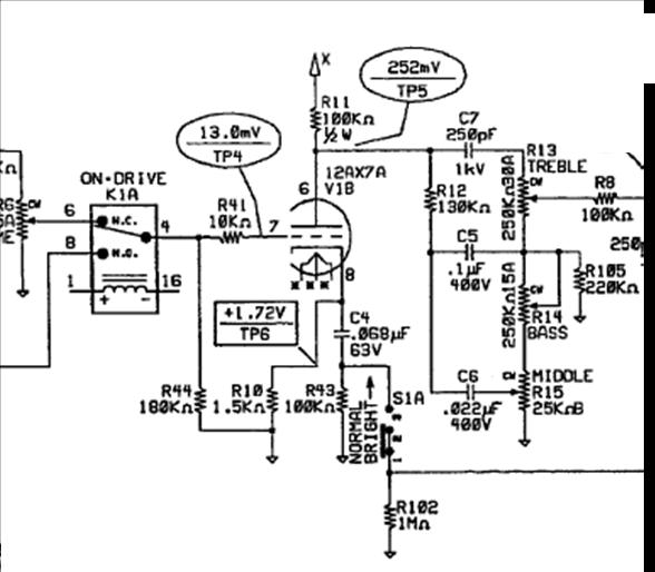
Let's start looking at stage 2 of the Hot Rod Deluxe Preamp. Some very interesting things going on, here, that we can take a look at. First, this is the stage where the "Bright" control has been implemented. So we'll take a look at how that goes. In the attached picture DOES NOT have all the components in it, for analysis of the "Bright" circuit, so you'll have to grab the schematic I told you to download. 8-)
The input, to this stage, comes through K1A, which switches from the voiced "DRIVE" control or the non-voiced "VOLUME" control. The output of the previous stage sees the input impedance of 180K, presented by R44. R41 is a "Grid Stopper" resistor designed to limit/stop the flow of grid current resulting from a high input signal from the previous stage. If you look through the "muck" on this stage, what you'll see is a Plate resistor RP of 100K, a cathode resistor RK of 1.5K. So, this stage, as per the other Fender stages, is biased right at the center of its DC load line for maximum input voltage swing.
The other tube circuit elements (C4/.068uF, R43 (100K), R102 (1M) are all for the "DRIVE" and the "BRIGHT" voicing. BRIGHT ONLY occurs on the Normal channel. DRIVE, of course, only occurs on the "DRIVE" channel.
So, when the amp is set to "CLEAN", K1B (just to the right of what I've actually copied" is set to the "N.C." pins (terminal 11 and terminal 13 linked). Terminal 13 is grounded and pin 11 is connected to the top of the 1M resistor. This has the direct effect of shorting the 1M resistor out making it ineffective when the "CLEAN" channel is engaged.
"BRIGHT" functions when the "BRIGHT" switch slides "up", as indicated by the arrow above the word "BRIGHT". When that switch is in the upward position, S1A effectively shorts out R43. This then shunts C4 (.068uF) directly across R10 (1.5K - cathode resistor). Using our handy 1/(2*pi*R*C) formula we find that this stage is shelved at about 1.5kHz, or thereabouts. So, yeah, it's "BRIGHTER" as everything below that frequency is gently removed.
When the amp is set to "DRIVE" pin 11 is "open" and R102 is inserted back into the circuit. As the resistance value of R102 is so high both R43 and C4 are rendered "ineffective" in terms of frequency response to this stage. When "DRIVE" is selected, this stage becomes a flat response stage with a bunch of negative feedback. It's very "clean" and very "linear", but it does add some gain.
No matter what, this stage feeds a 3-control, Fender-style tone stack, with some minor changes. R12 is larger than the standard 100K used in most Fender stacks, decreasing the impact of the Bass / Mid controls. The cabinet, on this amp, is SO resonant, this slope needs to be steeper to cut the amount of bass it produces. The "Bass" control, is only 250K, reducing the amount of "Depth" that can be added/subtracted by the Bass control sweep. The rest of the tone stack, however, follows Fender Bassman topology and is voiced somewhat similar to that amp. Fender was going for that basic sound when they developed this thing, though, so that explains it.
What mods could be accomplished here? Well, depends on what you're going for. You could remove the K1B switching altogether and leave the .068uF capacitor engaged all the time. Simply removing R102 and R43 from the PCB and jumpering from the bottom of C4 to ground (bottom of R102) would do that. You could change C4 to a larger value (.68uF for Marshall, or something else to suit your needs). Personally, I like the sound of the amp with the "BRIGHT" engaged and would just leave it at that.
By making this a permanent change, here, you're doing what MESA does and shelving out almost ALL of the lower frequencies. This would add a great deal more "articulation" to the amp when it's distorted. A .22uF capacitor here, in place of C4, would shelve at about the MESA frequencies. That would make the amp a bit more "blues" oriented, too, when distorted. It's just a thought. This stage has some power over the final voicing of this amp. Depends on what you're going for, in that category. You could move the "voice" down, toward 720Hz (Marshall) with a .15uF capacitor in this position - keeping the same mods as mentioned above.
If you're going more for the Marshall sounds, you can increase the treble cap (C7 / 250pF) to a 470pF capacitor and work with the value of R12 until you get the right balance of bass / treble for your liking.
That should take us to stage 3 of the HRD... we'll look at the "DRIVE" channel stage 3, V2A, just to keep out progression moving from left-to-right on the schematic.
Enjoy...
Dar
Dar, sorry I'm late to the party. We had company from out of town all weekend and I wasn't online hardly at all. Last night I sat down to go through this and quickly realized I couldn't follow along with the text without a schematic in front of me, and continually paging back up to look at it on here wasn't working. I'll print it out today here at work, and join in the fun tonight.
LOL... my opening remarks (d/l the schematic... and I even put the link up there). Although, you should be able to print the JPG's, too. :-) I have a dual-monitor system, here, so I put the schematic on one, and the explanation on the other. It's great. Very efficient.
Dar
yeah well, I was at home and couldn't print the schematic. In fact, gave me FITS at work. Could not get it sized right to get it all on the page. "Fit to page" "shrink to page" none of that worked. I'll try again tomorrow.
HRD - STAGE 3
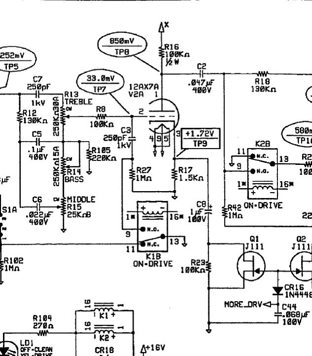
Here we go, into stage 3... the last time we were just leaving the tone stack, discussing the fact that stage 2 had either a 'voicing' that could be applied with the "BRIGHT" switch on the "CLEAN" channel, or it was a flat gain stage when "DRIVE" mode was selected. Stage 3 picks up where stage 2 leaves off. R8 (100K) is a grid stop resistor that limits both the current to the grid of V2A and also reduces the overall signal driving the grid on the tube. In addition, it acts in conjunction with C3, when needed, to create a low-pass filter to feed this stage.
Depending on the channel selection (DRIVE or CLEAN), C3 creates a low pass filter. When the amp is set to "CLEAN", the signal enters through R8, and then C3/R27 produce the low pass filter. Low frequencies are "boosted" below about 650Hz. When the amp is set to "DRIVE", R27 is byassed (shorted) by K1B. Then the 100K resistor (R8) and C3 form a different low pass filter with a shelf of 6.5kHz. This "softens" the end result, of the distortion. It also mucks with the clean channel sounds, as well, producing additional bass "boost" at this stage.
When either "CLEAN" or "DRIVE" is selected, the stage is setup, as per the previous stage, with virtually no cathode bypassing. That means the gain is constrained by the cathode-bypass resistor and is operating as linear as it can, right in the center of the load line.
When the "MORE DRIVE" function is enacted, a voltage is applied at the "MORE_DRV" pin (just below Q1/J111 - the FET). This turns on the FET which, in turns, shorts it from source to drain, effectively shunting (shorting) R23/100K. When this occurs, C8 is placed across R17/1.5K. This significantly increases the signal gain of the stage, as the Cathode resistor (R17) is now bypassed with C8. This increases the stage gain by roughly 6dB.
Some other things to think about, here. First, the input to the stage (R8/C3/R27) creates a low pass filter, rolling off the highs. R17/C8, in combination, provide a high pass filter, rolling off the lows. This stage has a "mid-hump" of roughly 900Hz, when the "MORE DRIVE" mode is enacted. When the "DRIVE" or the "CLEAN" mode is enabled the gain of the stage is much more smooth through the midrange, with a bit of a high frequency roll-off.
SOME MOD THOUGHTS FOR THIS PART OF THE AMP
Most folks that have this amp complain about the large amount of bass produced by the amp. Part of this can be alleviated by removing C3 and replacing it with a 1M resistor. Remove R27 and jumper the bottom of the new resistor to ground (base of R27). This would remove the bass boost, from the input of the stage, making it a bit more "clean", in terms of frequency response and allowing some of the highs through this stage.
Personally, I kind of like the "shelving" that occurs with the C8/R17 combination when the "MORE DRIVE" is enabled. So that could stay there. It improves articulation, overall. 6dB of gain is activated, in this stage, and another 6dB of gain is activated in the next stage, for a total of 12dB extra gain (a four times signal level - voltage - increase). So that's quite a bit. That much more distortion can get "mushy" if lower frequencies aren't removed.
So, overall, those are the two changes I, personally, might make to this stage. It would clean things up quite bit. If you want a bit more "sizzle", you could remove R8 (100K) and replace it with a 470K resistor and solder a 470pF capacitor (400V) to the bottom of the PCB. This would shelve the stage at 720Hz and provide a bit more "sizzle" when "DRIVE" or "MORE DRIVE" is enabled. It would also provide a bit more "sparkle" when "CLEAN" is enabled. It's just a thought.
So, all-in-all, at this stage, there is a "bass boost" at the input of the stage, through the use of a low-pass filter feeding the stage. When "CLEAN" or "DRIVE functions are selected, this provides a relatively smooth midrange, with a high frequency roll-off. When the "MORE DRIVE" function is enabled, this high frequency roll-off, coupled with the low-frequency roll-off that occurs from R17/C8 in parallel, serves to produce a 925Hz mid-hump, at the stage which then drives the final stage of the preamp.
Hope that helps... we'll be tackling stage 4, next.
Dar
i absolutely hate the drive and more drive channels on this amp. In fact now that im not living in a townhome and im able to crank this amp i hate the clean channel. this amp sounds great halfway up but after that its like an icepick to the forehead!! mine is totally stock though with all EH tubes.
HRD PREAMP STAGE 4 - THE FINAL STAGE
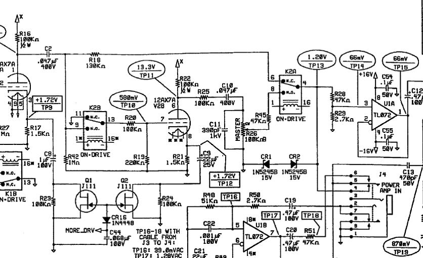
We're just about through the HRD preamp, in some level of detail. The 4th stage of this preamp is either used, or not, depending on the amp selections. When "DRIVE" or "MORE DRIVE" is selected, stage 4 is used. This works through the combination of K2A and K2B. K2A relay switch switches to pin 8 to pickup the signal from the "MASTER" control, and K2B switches to pin 9 to pickup the output of V2A, coupled from C2.
If "CLEAN" is selected, K2B opens up and no longer feeds a signal to V2B's grid. And K2A switches to pin 6 picking up the output from stage 3 and feeding it directly to the op-amp buffer (U1A).
Let's look at stage 4, in some detail... The combination of C2 (.047uF) and R42 (1M) form a high pass filter with a low frequency cutoff so low, it's considered flat response. So we're not going to spend any time on this part of the circuit. That is coupled into R20 (100K) and R19 (220K). This is a simple voltage divider, splitting off roughly 2/3 of the original signal voltage to feed to the tube V2B. V2B is the standard Fender gain stage with the 1.5K cathode resistor (R21) and 100K plate resistor (R22). The combination of C9 (22uF), Q2 (J111) and R24 (100K), make up another 6dB "boost" circuit. When the amp is in the "DRIVE" and "CLEAN" modes, Q2 is "off" and the 100K resistor (R24) is in series with C9 (22uF). This produces a stage with a large of amount of negative feedback, running very linearly. When "MORE DRIVE" is selected, Q2 is "turned on" and effectively shorts from source to drain. This "grounds", or "shunts" R24 leaving C9 as a bypass capacitor for this stage. It's a large value cap and, as such, pretty much produces maximum gain, across the entire frequency spectrum for this stage. This provides an additional 6dB of gain, here.
HRD FINAL THOUGHTS and NOTES
At the output of this stage, is another voltage divider consisting of R25 (100K) and the "MASTER" volume control (R26 / 100K). C11 (390pF) is used to bleed off high frequency noise, generated in the distortion stages of the preamp. This is a somewhat common practice in amps with distortion (though not Marshall's), to help "soften" the distorted tone and make it sound warmer. If the amp is too warm, remove the cap. If you want it a bit more "dull" you can put a larger cap in this location and more of the highs/mids will be shunted off to ground.
Honestly, that's about it, for this stage. We've learned most of the things that we can about this stage, from the previous one - the gain increases via switching a cap in/out by bypassing the 100K resistors, etc. Relatively speaking it's all pretty simple.
A few other notes, here. These days, you see a LOT of diodes in tube designs. You see them here (CR1, CR2, CR16, etc). A lot of regulatory bodies, nowadays, are requiring these things be put in for voltage/current limiting to protect from fires and accidental shocks/electrocution while using the amps. It's part of the reason why so many of the newer tube amps, built by companies that are tightly controlled (Fender, Peavey, Marshall, etc) have all that crap in them. It's just a note to be aware of.
The last part of the preamp, U1A, is an op-amp setup as an impedance converter, or buffer. It's job is to take the high impedance output of the tube, and convert it to an extremely low output impedance for the "Preamp Out". That way, almost all of the signal voltage, from the preamp, is used for the effects which, in the end, results in a greater signal to noise ratio for the effects and the power amp.
If the effects loop is not used the signal is tapped off just BEFORE the op-amp (right where it shows TP13, 1.20V). This is the signal that drives the HRD power amp.
I'm not going into detail on the power amp, here, as the HRD's power amp is pretty much a standard, 6L6-based, push-pull power amp, biased Class AB1, in which the power tubes are "ON" for roughly 75% of the full output cycle. When the amp is run at a lower level (i.e. about 75% of max, OR LESS) BOTH TUBES are operating FULLY on the signal. Remove one of them, and you have "Class A" until you run the amp full out. Interestingly enough, remove one of them AND you also "decouple" the power amp, as it renders the feedback loop ineffective. This makes the amp much more "spongy" and it's voiced a great deal more by the cabinet.
Enjoy... PLEASE ask questions, if you have them. Now that we've covered a lot of this, we can go into more detail... and discuss points, here and there, that you might want to cover. This is a great amp for mods/topology changes to. It's got enough preamp tubes to do the work, it's got the switching functionality, etc. This thing can be played with quite a bit.
Dar
WOW! I have to say, your experience with the HRD is pretty much directly opposite of what most others have experienced with the amp - new tubes, or old. Most folks complain of the overly bass-heavy resonance/response of the original combo cabinet and seek to hook the thing up to other cabinets with less bass resonance. So your experience is relatively counter to the experience of others of us that have the unit.
Compared to Marshall's, MESA's and others, this amp is relatively "low-key", and "bass-heavy" in terms of how the preamp and power amp is voiced. Marshall's are shelved a full octave higher in the spectrum BEFORE distortion is even generated. Distortion ONLY produces frequencies ABOVE the original, NOT below and the first harmonic generated (the 2nd) is 1 OCTAVE above the fundamental that created it.
MESA amps, as we've seen, shelve more than 3 octaves ABOVE what the HRD does, creating an even more "bass-starved" output. Because of this, MESA has to put in a ton of low-pass filters to get rid of the high frequency noise, and oscillation, caused by all of the gain and high-pass shelving in the amps. Those amps, compared to this, are even more "brittle" and more "ice-pick" in terms of highs, as a result of topology and design.
Anyway... I ramble... interesting perspective, though...
Dar
Mine was like he said above until I changed out the tubes and biased it hotter, from then on it rocked my world for a cheapo amp. I do play it through an open back extension cab with an EVM12L however.
DreamTheaterRules — Sep 05, 2008could be the speaker...
I am not overly impressed with the stock speaker, although it does not rattle the tubes like the EVM12L did when I swapped it out into the HRD Cab. Had to take it back out and put it in an extension cab, and reinstall the stock one. Good enough for jams etc but not if I really want tone.
For giggles I put in an Eminence Red Rang... I LOVE the tone on the thing, now. The stock speaker is a bit midrangey... there's a HUGE peak right at the edge of the "fizz" and "chainsaw buzz" region that's about 6dB hotter than most speakers...
Dar
I would have thought the Red Fang and HRD would go well together.
Actually, the Red Fang and the HRD go remarkably well, together. I put those Groove Tube Power Reducers (EL84's) in it. Those are biased to Class A (for real). With the reduction in output voltage being so great they have, effectively, removed the negative feedback loop around the amp. It makes the thing much more "dynamic" and "responsive" - very much like VOX AC30 - as it doesn't have any negative feedback, either. The end result was pretty darned ol' cool, to be totally honest. Plus, at 15 watts, I can actually get some range out of the volume control, and the Master Volume, to adjust the output, some. It's kind of neat.
Anyway... the Red Fang has stayed in the amp, for now. I did like the stock speaker, too, but I kind of like this "American British" flavor the amp has, now. It mic's up real nice and everything.
Dar