#1 · Aug 25, 2008 16:37 UTC
I thought I'd start this topic with the "Theory of Operation" taken right from Fender's own service manual and then add some comments, at the end. Here it is:
63 Fender Reverb
THEORY OF OPERATION
The input jack contains a Tip Shunt switch contact which will ground the input when the plug is removed.
The input impedance consists of R1R11 and R12 in parallel, and equals approx. 500k ohm.
The first stage (V1A) provides a voltage gain of 38.8 (V out/V in = 1.94V/50mV =38.8). Bypass capacitor C2
increases the AC gain, and also reduces hum. The voltage divider R2 and R3 reduce the voltage so the overall gain
is about 3. The signal then feeds the Dwell control, which determines the amount of signal sent to the reverb drive
circuit.
V1B provides a voltage gain of 20. C3 and R9 make up a single pole filter which provides 6db per octave of low
frequency roll off at 300Hz. Excessive low frequencies can make the reverb sound unnatural and boomy.
V2 is a 6V6GT power tube which supplies voltage and current gain to drive the reverb transformer. Due to the lack of
availability, the original 6K6 power tube was replaced with a modern 6V6. CR7 (56V Zener) protects C4 from
exploding if V2 develops an internal short. This is necessary to conform to modern day NEMKO safety requirements.
The footswitch turns the reverb on and off by grounding the input to the reverb recovery circuit. R13 provides a
ground reference (or bias) for the input of V3A. This prevents instability in V3A if the reverb recovery cable is
disconnected from the reverb pan. V3A senses the reverb return signal and amplifies it with a gain of about 37.
The Tone control (R17) attenuates the high frequencies above 3kHz, through C9. C10 provides a slight bass roll off
which is affected by the position of the Mix control in relation to the input impedance of the guitar amplifier.
V3B is a cathode follower, unity gain buffer amplifier for the dry signal.
C11 is a non-polarized, metalized polyester film capacitor, which is located across the high voltage transformer
secondary, suppresses EMI frequencies from 20kHz to 30mHz. This is necessary to conform to modern day NEMKO
safety requirements.
The pot mounting brackets are all connected together via traces on the circuit board. The trace connects to the star
audio ground through R22, R22 places 15 ohms of resistance between audio ground and the pot mounting brackets.
This is done for two reasons. Fist, with the circuit board installed, the pot brackets are physically connected to
chassis/earth ground. R22 isolates audio ground from earth ground through the pot brackets. This eliminates internal
ground loops. Secondly, when the circuit board is removed for repair and testing, R22 provides a ground reference
(15 ohms) for the pot brackets. R23 places 15 ohms of resistance between audio ground and chassis/earth ground.
This minimizes hum by eliminating ground loops internally and externally when connection with other units. R22 and
R23 are Flame Proof/Fusible resistors. If excessive current flows through theses resistors, they will not burn, they will
simply open.
CR5 & 6 (across R23) provide an important safety feature. IF the guitar amp chassis becomes electrified, current will
flow through the coax cable to the power supply ground of the Fender Reverb unit. The current will seek earth ground
through R23. When R23 opens, the earth ground connection is broken. This will electrify the reverb units ground and
thus the guitar (ouch!). CR5 & 6 provide an alternate path to earth ground if R23 opens.
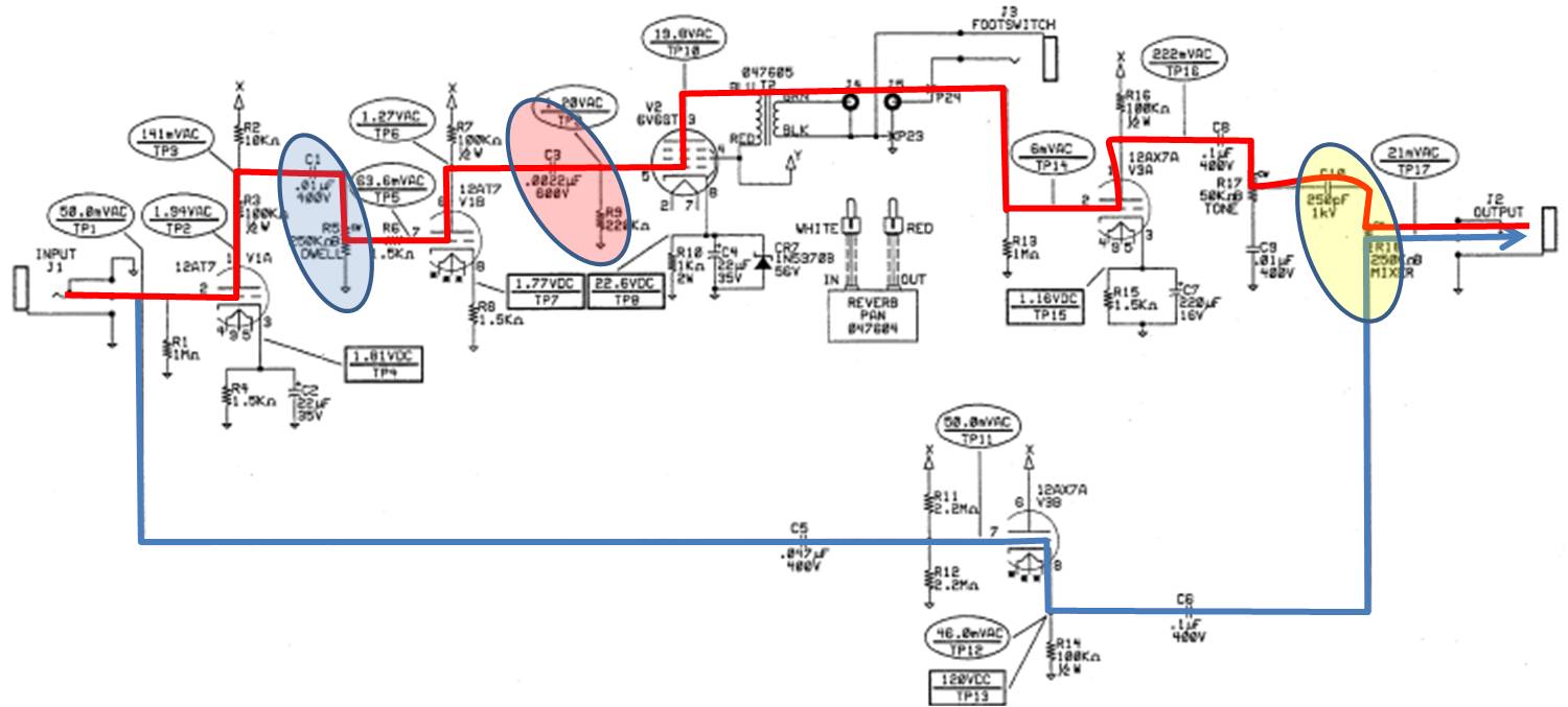
So, all of that said, there are some "defining" charactaristics, in this reverb that may, or may not, be in many of the other reverb counterparts. The first, has to do with the "driver" tube. In the Fender Reverb some sort of "power tube" was always used. In the attached schematic, a 6V6 is used. 6V6-style tubes were used in the originals. In most "standard" reverb units, this tube is a 12AX7 or 12AT7. The 6V6 can source higher current, mostly, through the driver coil on the reverb allowing for more signal to pass through the reverb coils with much less insertion loss than a standard 12A__ tube would be able to deliver. It is my feeling that this is the "core" element that makes this particular reverb more appealing than most of the standard reverb circuits that appear in most guitar amps.
Other highlights, though, in this reverb are circled. The first stage (blue circle) coupling network, (C1/R5 - Dwell) combination provide a 63Hz shelf (reduces low frequency hum in the initial design due to poor power supply regulation). The second stage coupling network (red circle) is a 325Hz high pass shelving circuit (attentuates everything below the "mud-range").
The stage feeding the tone control (C8/R17) is full range but the final stage (C10/R18 - MIXER) stage shelves the output at 2.5kHz (high pass).
I believe the frequency stages, in this thing, also, contribute to the overall tonality of the reverb unit, about as much as the higher drive current into the reverb tank does. Although I, personally, believe it's a combination of these two things that make this reverb unit so unique and so rich. Of course, having a good spring tank is essential, too. But any tank would be "transformed" running into this thing.
There are two signal paths, in this unit. The blue path is the original signal, which passes through a cathode follower (gain of "1"). This is the "dry" signal. The other signal path (red) is the "wet" signal which passes through the reverb tank. Both sides feed the "MIXER" control the wiper of which "moves", as the wiper is turned, closer to the "Dry" or the "Wet" signal feed.
Basically, that's the Fender Reverb unit, in a nutshell... ask questions if you have them.
Dar
63 Fender Reverb
THEORY OF OPERATION
The input jack contains a Tip Shunt switch contact which will ground the input when the plug is removed.
The input impedance consists of R1R11 and R12 in parallel, and equals approx. 500k ohm.
The first stage (V1A) provides a voltage gain of 38.8 (V out/V in = 1.94V/50mV =38.8). Bypass capacitor C2
increases the AC gain, and also reduces hum. The voltage divider R2 and R3 reduce the voltage so the overall gain
is about 3. The signal then feeds the Dwell control, which determines the amount of signal sent to the reverb drive
circuit.
V1B provides a voltage gain of 20. C3 and R9 make up a single pole filter which provides 6db per octave of low
frequency roll off at 300Hz. Excessive low frequencies can make the reverb sound unnatural and boomy.
V2 is a 6V6GT power tube which supplies voltage and current gain to drive the reverb transformer. Due to the lack of
availability, the original 6K6 power tube was replaced with a modern 6V6. CR7 (56V Zener) protects C4 from
exploding if V2 develops an internal short. This is necessary to conform to modern day NEMKO safety requirements.
The footswitch turns the reverb on and off by grounding the input to the reverb recovery circuit. R13 provides a
ground reference (or bias) for the input of V3A. This prevents instability in V3A if the reverb recovery cable is
disconnected from the reverb pan. V3A senses the reverb return signal and amplifies it with a gain of about 37.
The Tone control (R17) attenuates the high frequencies above 3kHz, through C9. C10 provides a slight bass roll off
which is affected by the position of the Mix control in relation to the input impedance of the guitar amplifier.
V3B is a cathode follower, unity gain buffer amplifier for the dry signal.
C11 is a non-polarized, metalized polyester film capacitor, which is located across the high voltage transformer
secondary, suppresses EMI frequencies from 20kHz to 30mHz. This is necessary to conform to modern day NEMKO
safety requirements.
The pot mounting brackets are all connected together via traces on the circuit board. The trace connects to the star
audio ground through R22, R22 places 15 ohms of resistance between audio ground and the pot mounting brackets.
This is done for two reasons. Fist, with the circuit board installed, the pot brackets are physically connected to
chassis/earth ground. R22 isolates audio ground from earth ground through the pot brackets. This eliminates internal
ground loops. Secondly, when the circuit board is removed for repair and testing, R22 provides a ground reference
(15 ohms) for the pot brackets. R23 places 15 ohms of resistance between audio ground and chassis/earth ground.
This minimizes hum by eliminating ground loops internally and externally when connection with other units. R22 and
R23 are Flame Proof/Fusible resistors. If excessive current flows through theses resistors, they will not burn, they will
simply open.
CR5 & 6 (across R23) provide an important safety feature. IF the guitar amp chassis becomes electrified, current will
flow through the coax cable to the power supply ground of the Fender Reverb unit. The current will seek earth ground
through R23. When R23 opens, the earth ground connection is broken. This will electrify the reverb units ground and
thus the guitar (ouch!). CR5 & 6 provide an alternate path to earth ground if R23 opens.
So, all of that said, there are some "defining" charactaristics, in this reverb that may, or may not, be in many of the other reverb counterparts. The first, has to do with the "driver" tube. In the Fender Reverb some sort of "power tube" was always used. In the attached schematic, a 6V6 is used. 6V6-style tubes were used in the originals. In most "standard" reverb units, this tube is a 12AX7 or 12AT7. The 6V6 can source higher current, mostly, through the driver coil on the reverb allowing for more signal to pass through the reverb coils with much less insertion loss than a standard 12A__ tube would be able to deliver. It is my feeling that this is the "core" element that makes this particular reverb more appealing than most of the standard reverb circuits that appear in most guitar amps.
Other highlights, though, in this reverb are circled. The first stage (blue circle) coupling network, (C1/R5 - Dwell) combination provide a 63Hz shelf (reduces low frequency hum in the initial design due to poor power supply regulation). The second stage coupling network (red circle) is a 325Hz high pass shelving circuit (attentuates everything below the "mud-range").
The stage feeding the tone control (C8/R17) is full range but the final stage (C10/R18 - MIXER) stage shelves the output at 2.5kHz (high pass).
I believe the frequency stages, in this thing, also, contribute to the overall tonality of the reverb unit, about as much as the higher drive current into the reverb tank does. Although I, personally, believe it's a combination of these two things that make this reverb unit so unique and so rich. Of course, having a good spring tank is essential, too. But any tank would be "transformed" running into this thing.
There are two signal paths, in this unit. The blue path is the original signal, which passes through a cathode follower (gain of "1"). This is the "dry" signal. The other signal path (red) is the "wet" signal which passes through the reverb tank. Both sides feed the "MIXER" control the wiper of which "moves", as the wiper is turned, closer to the "Dry" or the "Wet" signal feed.
Basically, that's the Fender Reverb unit, in a nutshell... ask questions if you have them.
Dar