#1 · Aug 29, 2008 15:21 UTC
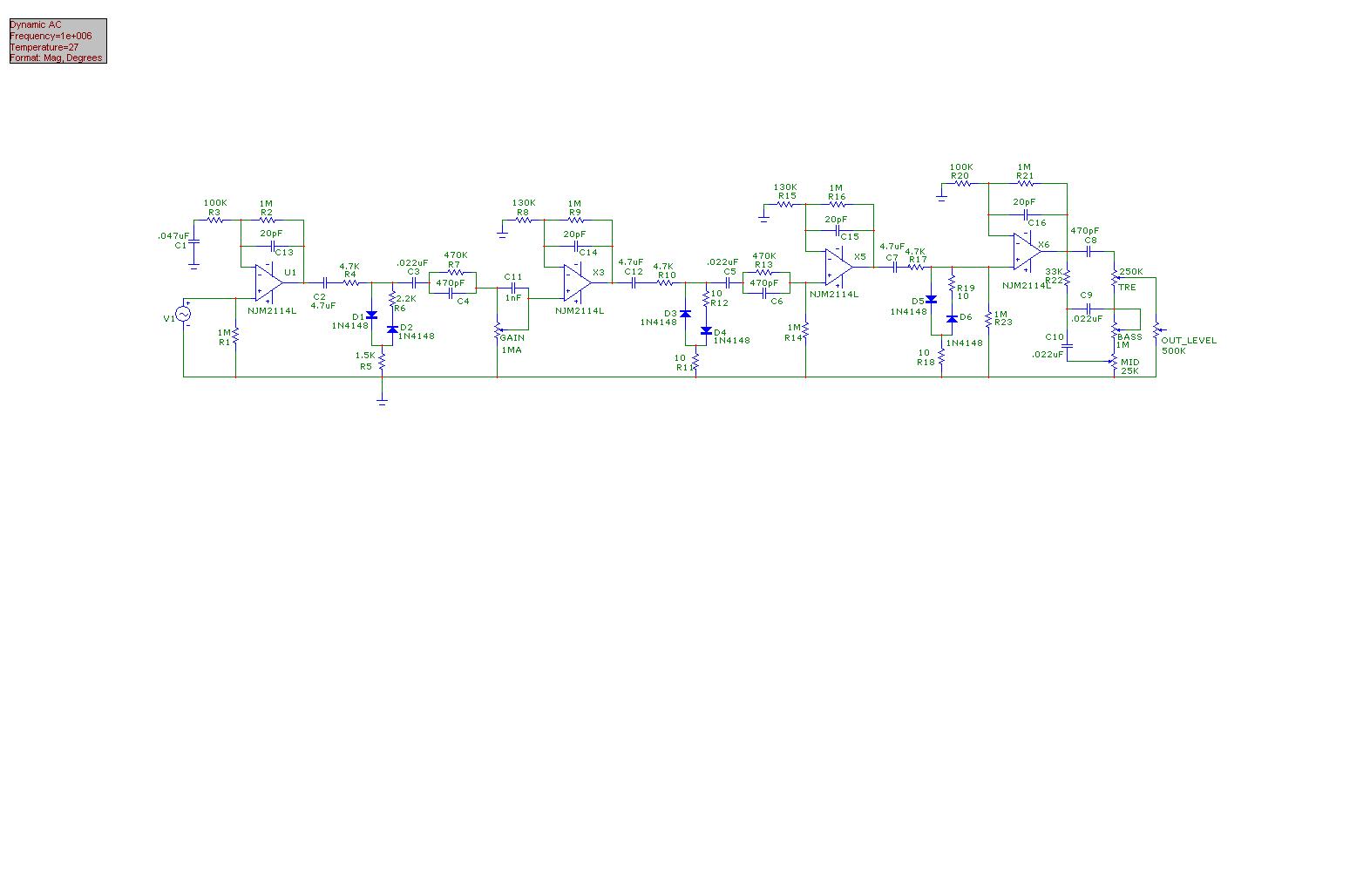
Here's a challenge for the DIY pedal builders - build a JCM800-like preamp, complete with distortion generation, etc. There are a few points of interest, here. First, I'm using dual 9V supplies for the op-amps, that puts my output rails at about 7.75V peak. I chose the NJM2114's because they're ultra quiet, clean and relatively distortion free, of themselves. Most of the distortion will be generated in the diode clipper circuits.
I am using what is often referred to as "compliance" circuits, for the diodes. Let's look at this circuit in a bit more detail. U1 (on the left) is the input op-amp. It has a 1M input impedance (R1). The gain of the circuit (AC/signal) is created through the use of R2 (1M) and R3/C1 (100K/.047uF). This creates, as in the Marshall, an 86Hz high pass filter. C13 (20pF) is there to create high frequency stability for this gain stage. If it's not there, the stage will oscillate. This stage is designed to amplify a standard guitar signal almost to the rails of the op-amp.
C2 is a DC blocking cap. I found that the 1M input resistor, coupled with the small offset current, at the input, actually created a high enough DC output voltage to goof up the clipping circuits. I'm using WIMA FKS/FKP film caps through this entire thing.
The "beauty" of the circuit lies in D1, D2, R6 and R5. D1/D2 generate distortion, as the diodes clip. I'm using 1N4148 diodes which have a relatively "smooth" on transfer function. If you look at their "on" curves, they look like a tube plate curve. R5 (1.5K) is designed to "raise" the voltage at which the diodes actually turn on. Because all guitar amps have virtually no distortion generated in stage 1, this value is very high. The lower the value of this resistor the "faster" the onset of the clipping.
R6 is placed in series with one of the diodes to further change the "on voltage" of that diode. This then provides the standard asymmetry that would normally be experienced in the tube circuit. You'll notice that the diode orientation changes every stage, in this design. It's due to the fact that each op-amp is setup as a non-inverting stage. Tubes invert the input signal. Thus I've changed diode orientation to match this.
Other challenges... because Marshall distortion is primarily generated in stage 3, rather than stages 1/2, stage 2's compliance circuit needs changed to reflect that. Right now it's biased "hot" so that the diodes turn on much more quickly than what they need to. R11 value needs to be increased more toward the 1.5K. R12 should also be increased twoard the 2.2K value that's in the preceding circuit - though not quite to those values as there is some distortion experienced in this stage, in the Marshall.
Stage 3, however, can remain as it is... as this provides the most clipping in the Marshall. For slightly more asymmetry, you might change R19 to a higher value (22 ohms, 33 ohms, 100 ohms, etc).
All the stages were setup, here, to basically accept the voltage input, from the previous stage and bring the signal level (cleanly) to the voltage rails of the op-amp so that distortion could be generated/controlled within the clipper circuit.
If you want a more FET-sound, you could substitute the NJM2114's for TL072/TL082 op-amps. That would work just fine. This unit generates enough output voltage to plug directly into the power amp in on most guitar amps. Yeah, it's got that much output.
This version, here, works pretty well, overall, though due to the fact that I'm distorting in both stages 2 and 3, rather than primarily in stage 3, it gets a bit more "symmetric" distortion and runs more toward the "MESA" and/or JSX/XXX style distortion rather than the slightly more 'crunchy' version of the Marshall.
There you have it... build it and have fun. I like building these from op-amps rather than FET's (like Runoff Groove does) mainly because FET's are so finicky. Op-amps, you just slap resistors/caps around them and every op-amp behaves the same way. FET's need a TON of adjustment and care.
I've built this one, just for fun... and it sounds pretty... let's have a challenge and have a few more of the DIY folks do something like this and see how it turns out... we can work a forum post just to "tune" it.
Dar