Due to Sir Howard of Customshopdem's trigger happy nature with deleting post's ( ::)), I'll start this again but on two fronts.
1; software tools and
2; physical tools (another thread)
Cool tool for designing curcuit boards.
http://www.storm-software.co.yu/diy/index.php?project=softwareCool page from the same guy with lots of curcuits already sorted for you.
http://www.storm-software.co.yu/diy/index.php?project=layoutsA great site with lots of basic info.
http://beavisaudio.com/techpages/SchematicToReality/Hope these help and long may they stay around, eh Howie....? ;)
I tried to delete one post that you asked me too, and now I'm a stooge! :-[
I'm staying out of this one! ;)
As moderator you are bound by the rules to add something of worth.
I, for my part will, will try not to screw up my posts and make your life easier. Hows that? ;)
Bout time! ;D ;D
I'm going to create a dummy thread later and see if I can make sure what happened, so it doesn't happen again. Dang, I wish I had just told you to edit your own post. You can go back and remove an attachment. Since all you wanted was that pic out, I wish I'd done that instead. But we'll get it figured out.
Here's a boost curcuit I robbed from the Bevis site and used the DIY layout creator to mess with and see how easy it was to use. Took me about half an hour to do this which is not bad considering it was the first time I had used it and the fact that I know nothing about this kind of thing.

Maybe Dar could give it a once over and point out any mistakes I've made before anyone else goes trying to build this.
Actually Dar, could you confirm that this would work as I have a couple of empty enclosures and all the bits lying round to build this.
To further this Dar, how would I go about putting a tone control in this curcuit?
well, I have answers but, I'm not Dar. :P
:D
if I were Dar, one thing I'd say....
"breadboard"
But I didn't say that. ;)
That IS breadboard Howie!!!
I meant, if you want to test the circuit, breadboard it first.
Second, that picture is PERF board.
Ok, H. Having looked at the Bevis site again (in an effort to prove myself to be right ::)), I now see the difference between bread and perf board.
Point taken and I concead.
I'd still like Dar to jump in on this and varify the curcuit and explain how a tone control would/should be encorperated, mainly for the benefit of others. (Pointless having to control holes in an enclosure if you dont use them ;)).
DAR!!!???
LOL, well, it wasn't an "I'm right, you're wrong" type thing. Just pointing out that there are 3-4 types of boards you can build this stuff on. This one is a perf board... nothing but a board with holes. Meaning all parts must be connected, as you indicated. A breadboard is actually "sorta" like strip board. In that, to join to parts, you just plug them into the same "line" in the grid, because that line is all connected. So, you put one side of a cap in line 4, hole 1, and then anything you put in line 4 hole 2 (3,4,5 etc) is where the signal would flow from there. YOu don't have to physically connect them, solder them together, etc. That's why breadboarding is so good for experimenting/testing. You don't even have to trim the leads of parts! Just create the circuit by sticking the parts in connected strips and there you go.
Also... I don't want to butt in on the tone control, but if I were Dar, I'd say that there is a thread called something like "add a tone control to any pedal" at BYOC. LOL And if I were Dar, I'd say, remember that any time you add even that simple of a tone control, you will have some gain loss of the circuit. But, I'm not Dar so I won't say that. HAHAHAHAHAA
p.s. I could even find that post, put up a pic of the tone control, and then Dar could comment and tell you where to stick it. ;D (seriously,it might be at Beavis too. He and BYOC contribute things back and forth to both forums).
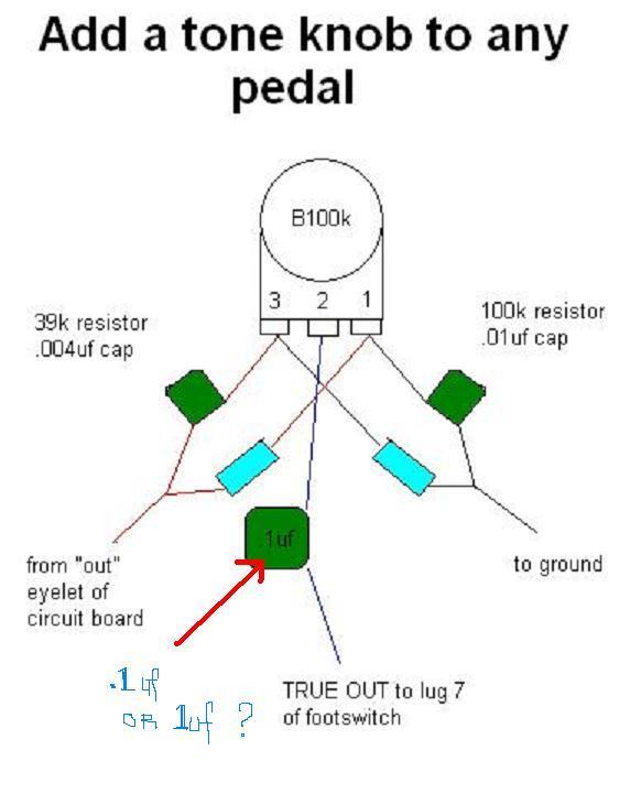
ok, here it is... The tone control out of the Big Muff, with some interesting notes from Keith at BYOC...
That's a scooped mids Big Muff tone knob. If you change the .004 to .01 you can get flat mids. If you swap the .004 and the .01 you can get a mid hump.
OK... so I've been "out of touch" here, for a few days. And, after tomorrow, again for a couple of weeks as I head to Montana... ride horses and chase 200 cows through a 75,000 acre (not a typo) pasture in the mountains! I need some time off ::) and, somehow, find this type of work relaxing. Plus it'll give me a chance to try out all the things I've learned, this year, training and working with my horses.
So, ummmm.... where were we??? :-/ oh, yeah, tone controls on booster circuits. So, I hate having to look at pictures of what could be a schematic, but I did draw the thing out... a standard "CE" (Common Emitter), BJT (bipolar junction transistor). I haven't plotted the gain, on the thing, but it will produce some gain, at least.
With regards to "tone control", what are you hoping to accomplish when all is said and done? I see that the Big Muff Pi circuit was posted as a possible solution - although that thing is a bit cumbersome for a simple transistor circuit, IMHO. Were you looking just to roll-off the highs? Wanting a "mid-scoop", a "mid-boost", "bass boost"?
As per Howie's comment, a "tone control" of any type creates what is called "insertion loss". A typical tone circuit will take the boosted signal (after gain) and knock it down to about 1/2 of the original input signal - on average. That means, typically, that you're going to need another stage of gain, AFTER the tone circuit to build that signal back up for output into the next gain stage. Otherwise, you'll end up with a very weak output, to say the least.
Finally, a couple of other things, here... just a thought. First, the lower the output impedance, the BETTER the signal voltage will "transfer" to the next pedal, preamp, behind it. This particular design has a high impedance output (poor voltage transfer). An additional stage (buffer stage) should be added. It can either be an FET, BJT or op-amp design.
I have included the schematic for the Seymour Duncan Pickup Booster in this link (http://analogguru.an.ohost.de/193/schematics/SeymourDuncan_PickupBooster.gif). This provides 25dB of gain (a gain of 17.5x the original signal). This is another approach. Q3, in this design, is the "output buffer" that coverts the high impedance signal input/gain stages to a low-impedance signal output.
Anyway... I digress, back to the original topic - what tone shaping are you truly needing/wanting for this circuit? I have, also, included the schematic for the Seymour Duncan TweakFuzz (a very good pedal). This one has a 6-position switch on it, that selects the input circuit (frequency dependent) for tonal shaping (C1 - C6 and R1 - R6). As this occurs BEFORE amplification, you'll get a good signal boost out of the circuit AND you'll probably get all you want/need for feeding the amp following. This provides a very good range of "shelving" options which would range from a "Treble Booster" (RangeMaster) type of input all the way to flat response.
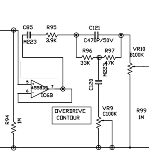
Those are some thoughts/ideas. Personally, I'm not much a fan of the Big Muff Pi implementation. If that's what you're going for, then, by all means, do it. :-) Another suggestion is the Marshall "contour" circuit - attached. This one does a great job of sweeping the range of frequencies and providing some nice contour selections.
Dar
I love what the contour control does on my Jackhammer.