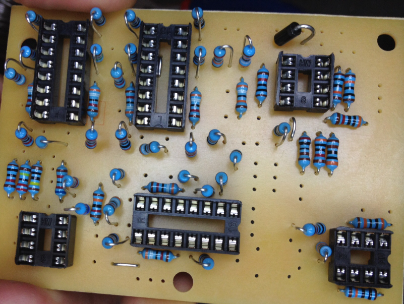
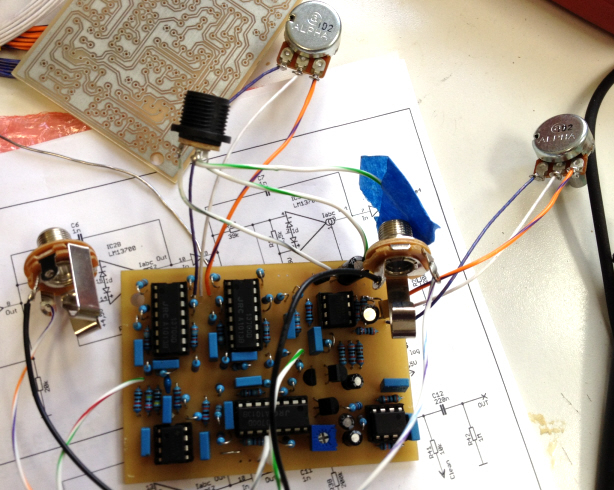
Building the Maestro phaser, to replace my unbelievably killer Maestro Phaser, which, although unbelievably killer, is way too big, unwieldy, and rare to drag to a gig or to fit in a pedal board. This is a complex build... it's got 53 resistors, three 16-pin dual OTAs, three 8-pin op amps, many caps, and it's all on a tiny 2"x3" board, so it can fit in a 1290 case. Boards were etched from someone's post I dug up. With the help of my electronics guru we made some corrections on the fly... here it is with the resistors, diode, and sockets in. As you can see to fit on this board many of the resistors are installed standing. Caps go in tonight, along with several on-the-fly fixes. If this works I've etched 4 more boards, and have parts to build 5... total cost including etching, cases, and all parts is right around $45 per pedal.
Etching boards now??? you are hooked!
Very nice looking build so far.
Tracing out the circuit my buddy realized that the noise filtering was not going to cut it... the original Maestro used a .1uf ceramic cap at the input to the second stage of this opamp. Sufficient to filter high end noise but not 60 Hz. The redrawn schematic used a 47uf cap to capture this 60Hz, but because of where it sat in the circuit it was innefective and nearly pointless. implementation was all wrong... and I quote "C14 is completely useless where it is. The op-amp's output impedance is in the fractional ohms range, and even if it were 1 ohm, the cap would only minimally affect frequencies above 16k. At this frequency, the electrolytic's ESR dominates the equation, so it would actually have zero effect on any frequencies. I.e., the cap is effectively out of the circuit."
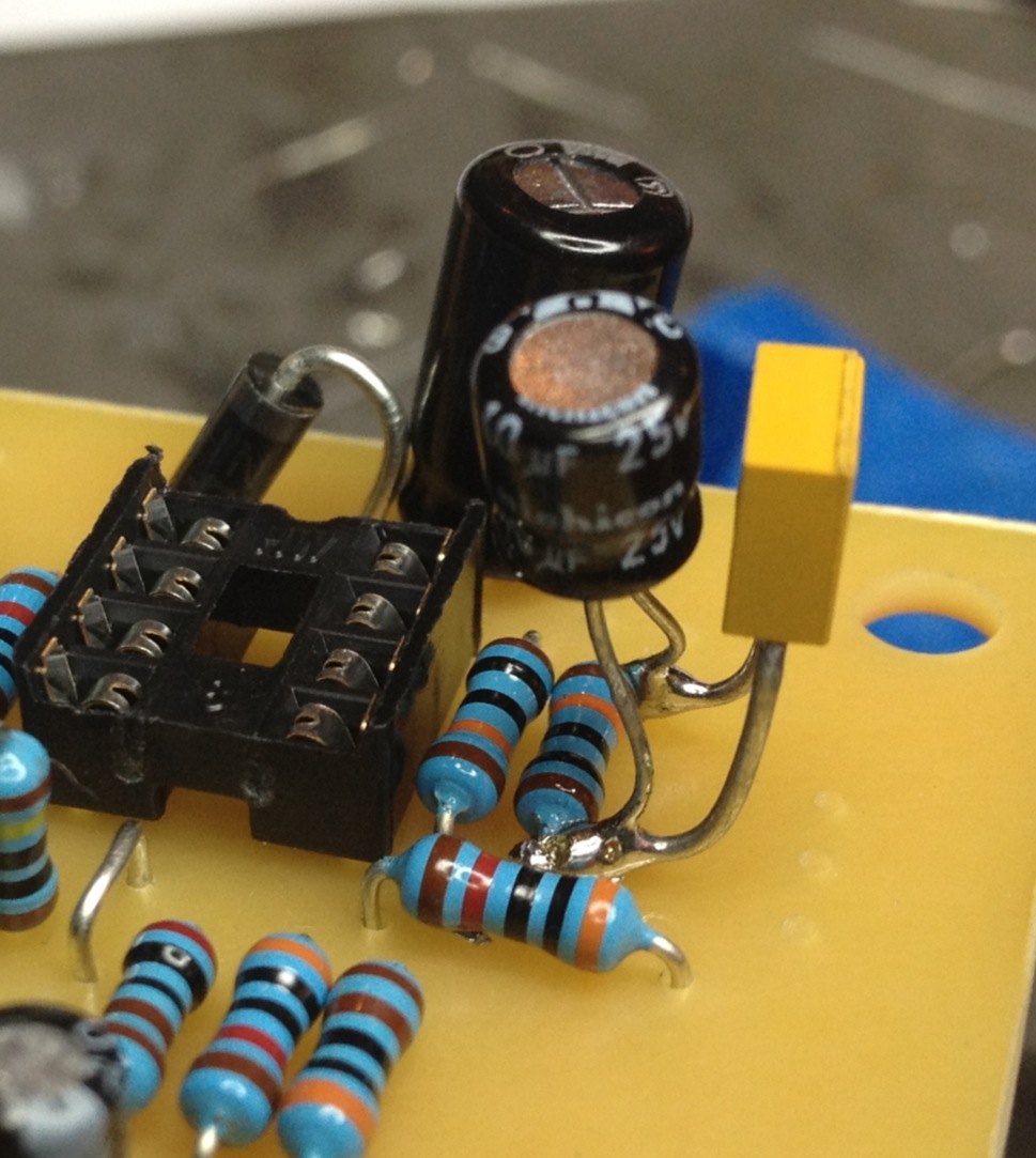
The solution was to stick a 10uf electrolytic across the resistor between the opamp input and ground to drop 60Hz noise... and to also use a .1uf ceramic in parallel to shunt high frequency noise to ground.
This falls under the category of "cool fixes thanks to people smarter than I".
It also falls under the category of "goddam that iPhone camera is amazing".
First completed Maestro clone works after a couple hours of troubleshooting... I learned quite a bit from this build and the next 4 should go much more easily. It's a beautiful circuit but very, very tight and lots of very miniscule stuff in the soldering.
Here it is... at this point, the ground and +9v on the dc jack were wired backwards... I didn't notice until a couple minutes later when I started testing voltages and they were all negative...
Looks like you're almost ready to upgrade a few Rockman units! ;D
Wow, that is a TIGHT build!!! These old eyes probably couldn't hand that. LOL
Looks great so far!