47 posts
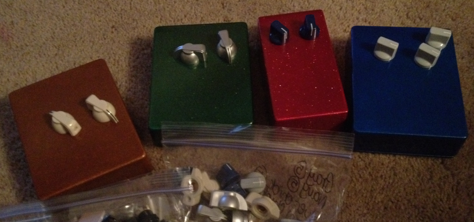
Parts are showing up... here are some pedal enclosures I bought recently... I've got another five... and I've got 4 pedal projects in the works...
Also in the pic, some knobs and jacks...
ok, spill. What are the projects?
I'm doing a ross-style comp, two big muffs (one with germanium clipping diodes, one ram's head), and a shredmaster so far. Thinking about an analog delay, an optical comp, and a tubescreamer.
I KNEW you'd be doing a muff or two. Might want to check a Mayo spec'd one. Many guys at BYOC who have tried them all, say the Mayo sounds the best.
Where are you getting your boards and build info?
build your own clone, mammoth, and all over the web. I think after consideration I'm actually going to make a super muff with a toggle to switch between silicon and germanium clipping diodes. I might make it a 3-way and do LEDs too...
Nobody makes a toggle switch that switches between three different things. Nobody! How f'ing annoying. So I think my muff will switch between Ge and Si diodes only. I could use a rotary switch and do all 9 combinations of silicon and germanium and LED in the two gain stages but instead I guess I'll just do ge/si in each position, two switches, two positions each.
Um... Almost every LP style guitar I've own had three way toggles... :-?
They can't be made to do three different things?
those toggles aren't "three way" in that sense - they are in a combinatorial sense though, ie, they use three of the ways to combine two things that can have two states. off/on, on/on or on/off. the other option, off/off isn't used much but could be - however that would limit you to on/off, on/off and off/off... or off/off, off/on and off/on... killswitch in one of the positions.
Charger, they are out there. I have some and I'm sure Jorden does. Google"on-on-on"switches.
You actually think I haven't done that? on-on-on doesn't give you the choice of three different options... the middle "on" position is one leg of the top position and one leg of the bottom position... there's no way to get three completely separate circuits with a DPDT switch...
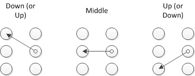
Here's the switch I want, that no one makes...
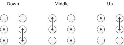
Here's how a DPDT on-on-on switch works.
Like this:
http://www.smallbearelec.com/Detail.bok?no=495Looked like Mouser had DP3T and SP3T in more normal packages, as well, but more expensive...
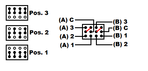
Nope, same issue with any on/on/on switch I've found. Here's the connections for a dp3t on/on/on
I think these werk like the schem in this pdf:
http://www.mouser.com/catalog/specsheets/TW-700095.pdf
wouldn't a jumpered DPDT on-on-on do that?
used this in my ludicrous ibanez wiring scheme... can't remember how or why, but I used it for something (heh).
found a picture:

I think your logic is sound. Good find! I swear I looked at a similar image and completely missed it... maybe because it's labeled sp3t and it's really dpdt it didn't show up in my google images search...
just saw this, on my way out the door. If I understood correctly, you want 3 clipping options, right? Definitely switches that do that, just harder to find than on-off-on toggle switches. They are out there and I have some. If you just need one or two, I'll give you a couple.
cool, hope it works!
the only other idea I had was to use a slider switch.
No, it's all good, I've got dpdt on-on-on switches and I've been scratching my head over how to get exactly that out of themm was a couple hours away from using an on-off-on and relying on the shunt ability of the lower forward voltage diodes to override the LEDs. You nailed it--now I can implement it the way I want, with trim pots on the silicon and LEDs to balance the volume between the three modes...
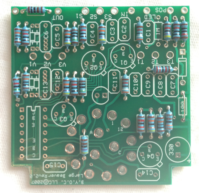
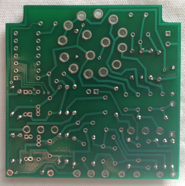
rear shot of resistors... i'm pretty happy with my soldering on this, got a new iron a few weeks ago that makes it so much easier.
looks pretty good. What iron did you get?
http://www.circuitspecialists.com/soldering-stations-csi-station1a.html
Recommended by people on the general guitar gadgets site... $30 and when you spend $50 at the site you get a free DMM... not bad. Anyway, compared to every iron I've had, including two low-midline Wellers, it's a godsend. Keeps its heat well, flows solder really well even into those tiny joints (this pic is probably 2x life size). Came with a really nice sharp tip, I bought a couple more fine ones as well but am still on the included one. I set it high--700 degrees--and then do fast joints, heat the pad and wire for 4 seconds then apply solder. I much prefer high heat/fast to low heat/cooking forever.
yeah, I've seen that one recommended before.
And yes, higher heat-faster solder is good. Just don't linger. You can lift a trace faster with a hot iron. But they BYOC boards are VERY good. Most of the plate through boards are safe unless you really mess up. The board looks like you've bot it down though.
I've done lots of soldering but never on anything so small... the advantage of the tiny iron tip and the controllable heat makes it pretty easy...
yeah, it can look intimidating at first... I bought a lighted magnifying glass and its a piece of cake.
One thing on soldering in such small boards and so close together... lots of guys say only do 4-5 at a time, or if they are lined up, one line at a time, then let the board cool, then do more. Don't do it all at once or even with quick joints the board can get hot.
yeah I take a section at a time.... 3 or 4.
I think I'm going to socket all of my transistors, I have a bunch of those single-point sockets. for portability, and because I really don't want to be heating those things up. I probably should socket my Ge diodes too, those things are fairly heat sensitive.
that plus you can experiment easily if you socket them. Are these matched or rated at all?
the transistors?
It's a big muff... transistors actually don't play much part in the clipping, it's all about the diodes. The Germaniums are not matched or rated, no, the physical properties are known, there's a .3v forward voltage drop with Ge, .7v with Si, around 1v with LED, which basically translates to the Ge clipping the fastest but being the quietest, the LEDs clipping the least but being the loudest.
Yeah,i know all that,even the specific clipping voltages, but the trannies determine the gain structure. There are preferred gain ranges, and even preferred places in the circuit for the range of gains you have to use.
Anything high output will work, you can certainly change the volume but the clipping in a big muff is a function of voltage and the clipping diodes... EH swapped transistors around willy nilly, even within the same rev of the box. The one that sounds different because of the amplification in the circuit is the opamp version, the one that's all over Siamese Dream.
The transistors that came with the kit are very high gain... I was surprised when I stuck them on my meter. hfE around 485. As a comparison I've got some old Russian germanium transistors that have an hfE of around 50.
Right, I know any high gain will work. Just saying, the guys who have built many, and different versions, over at BYOC, have preferences for gain ranges, and certain places to put them... example: I've seen at least 4 or 5 guys there (who have all built many) say to put your highest gain tranny first. I've seen at least 3-4 of them say that they prefer mid 500s for gain on them.
Also, many love the Russian spec one, and the rams head, but those who tried them all, almost all of them say the Mayo is the best. That would make sense since Skreddy is a TOP flight builder.
I'm not saying there is a right or wrong on these things. Just sharing preferences of some pretty advanced builders.
I'm a fan of the Civil War muff, and the Ram's head. I'm doing a Ram's head first, with my clipping diode swaps, and a couple of other tricks. Civil war next.
COOL. Can't wait to hear them.
Me neither!
I hope I get some time to work on the super muff this weekend... the one time I am actually regretting that it's poker night tonight!
I didn't take a pic of the guts because I just finished it last night at 2 AM and I just spaced on the gut shot. I will say that my wiring is somewhat messy... a little planning next time will make it cleaner. But here's the clipper test rig. Essentially, I've socketed the two diode clipping stages in the Big Muff, and I'm running test leads from the each one, then I will use this board to test each diode/LED pair as a clipper in each stage. Hopefully I'll find three I like in each spot, or in combination, then I'll wire them to a piece of perfboard and throw them on the three-way switches (thanks to ironsheep for clearing that switching crap up for me). I hope to have this done by Sunday... my sister-in-law is taking the box to paint on Monday.
Cool pics! Like the bread board tester too. :)
yeah, breadboard is the way to go. This is exactly how it's supposed to be done. This may sound silly... (as in you probably already know this) but give each clipping set a thorough test through the whole drive range. This will allow you to see how the different cutoff voltages affect their clipping performance.
I only say this because, as an example, I've seen lots of guys try germanium clippers and write them off quickly because they aren't as loud... well, that's because they clip at lower voltages. Turn the volume knob up with them! Many find their clipping more appealing. Plus, clipping at lower voltages can give a smoother tone (clipping earlier effectively equals compression) and this can be a good thing for "solo" pedals, etc. So yeah, your volume setting may need adjustment between your LEDs and your 1n34s, but it can be well worth the trouble.
Also, if you find that you like 1n34s but that difference is just too much, but you otherwise really like the sound, try a higher voltage germ, like a 1n60.
lastly, I see (appears to be) lots of matched pairs. Mixing (=asymmetric clipping) is your friend! Try it! Many say it is the most tube like...
DreamTheaterRules — Nov 17, 2011 I only say this because, as an example, I've seen lots of guys try germanium clippers and write them off quickly because they aren't as loud...
Yeah, these aren't loud at all! ;) :D

those are tungsten, which has different clipping characteristics altogether, and should be used with extreme caution while gardening naked.
DreamTheaterRules — Nov 17, 2011yeah, breadboard is the way to go. This is exactly how it's supposed to be done. This may sound silly... (as in you probably already know this) but give each clipping set a thorough test through the whole drive range. This will allow you to see how the different cutoff voltages affect their clipping performance.
I only say this because, as an example, I've seen lots of guys try germanium clippers and write them off quickly because they aren't as loud... well, that's because they clip at lower voltages. Turn the volume knob up with them! Many find their clipping more appealing. Plus, clipping at lower voltages can give a smoother tone (clipping earlier effectively equals compression) and this can be a good thing for "solo" pedals, etc. So yeah, your volume setting may need adjustment between your LEDs and your 1n34s, but it can be well worth the trouble.
Also, if you find that you like 1n34s but that difference is just too much, but you otherwise really like the sound, try a higher voltage germ, like a 1n60.
lastly, I see (appears to be) lots of matched pairs. Mixing (=asymmetric clipping) is your friend! Try it! Many say it is the most tube like...
Yep I know. For the volume issues, I am planning to add resistor trimpots to each diode stage that needs it, to get the volume similar between all stages. LEDs will be much louder though I may not even use them. However, I've got so many germanium pairs I might not have any volume issues... this could very well end up being an all-germanium pedal. You may have missed it from the visual inspection, but in addition to the 1n34s (green bands) I've got 1n60, 1n270, 1n277, and those black ones are Ge as well--5 sets of Ge! There's also the standard 1n914 silicon, some very beefy zener silicons, and two different sets of LEDs (though I may standardize to red LEDs, red has the lowest forward voltage and therefore probably better clipping... I don't think I want a "clean" muff). If I can't find 6 usable settings with these pairs, I may very well go assymetric... one idea I had was two germaniums in one direction, silicon in the other, or two Ge to 1 Ge (some people mod TS808s this way)... But man, I am hoping I find the sounds I want before I get through all the pairs... it's going to require a spreadsheet.
yeah, sorry about that. I didn't think about what pedal it was til after I posted. Asymmetric is mainly effective in screamer or D+ or circuits with less gain stages.
I didn't look closely enough to see what all was on the board.
I am heavily biased towards germanium...