#1 · Aug 27, 2008 21:28 UTC
Howie brought up two topics in one, in the "where to next" topic I posted a while back. First, he wanted to discuss what occurs within a tube when the "gain" of the tube stage is changed. He also wanted to address what happens to a tube stage when it's hit with more gain (i.e. higher signal level). He may not know it, just yet, but his question actually was two-headed. :o
So, let's take a look at each one independantly. Howie's first "question" has to do with "tube bias" or "operating point." I have alluded to this topic a few times, in the past, and I'll touch on it, again, here in this particular post. The way a tube is biased (i.e. the voltages applied to it, to make it operational) determines how linear the tube is. In a typical preamp stage the tubes are, typically, self-biased - meaning the only a single voltage is applied to the plate and the rest of the circuit "biases itself" as a result of that plate voltage. This is done through the addition of a cathode resistor.
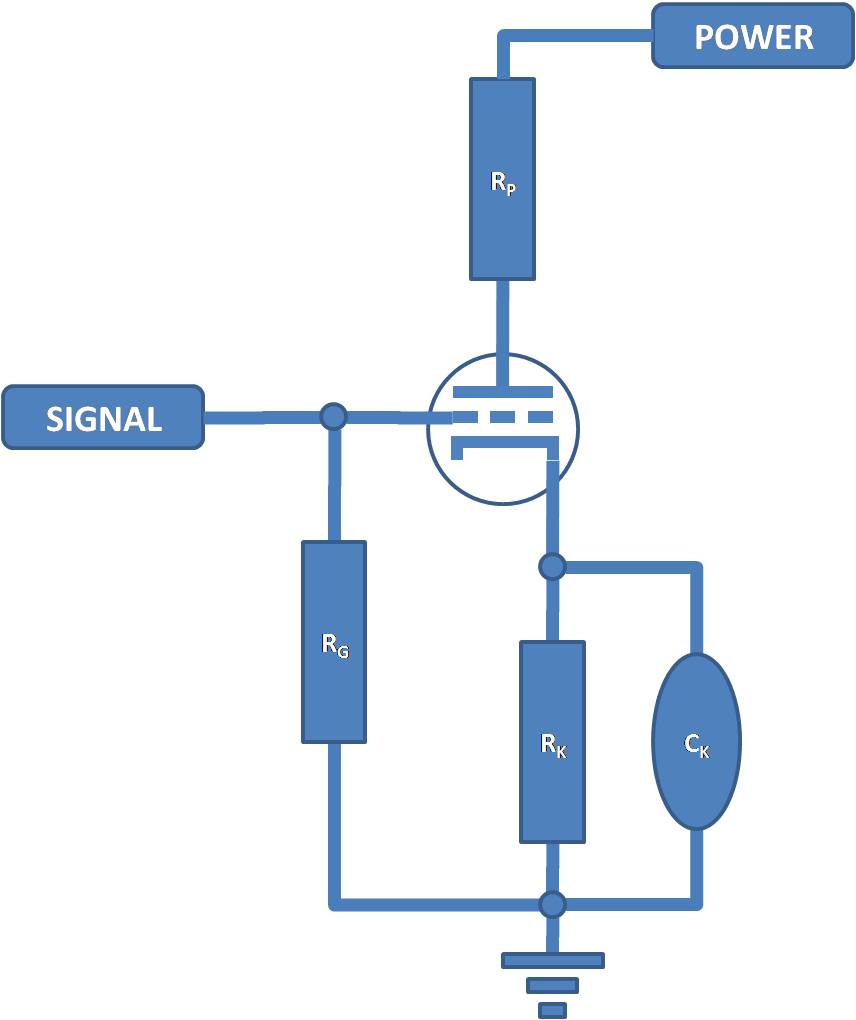
To that end, I have included a file that outlines a basic tube stage, with all of the components added in. There are two things, in this design, that need attention. The first is the DC, or "static", operating point. This generates the baseline voltages and currents for the tube. The other is the "small signal parameters" or, in older tube books the "dynamic charactaristics" - i.e. when the signal is present.
The static operating charactaristics are derived by the resistances around the tube. In a Fender tube stage, a 12AX7 tube is used. In the Rp spot, a 100K resistor is placed. In the RK spot a 1.5K resistor is placed. These two resistors, combined, create the DC, or static, operating point. The plate resistor (RP) sets the maximum plate current obtainable by the tube stage. A larger plate resistor = less plate current (Current = Voltage / Resistance, where a larger resistance = smaller current). In the tube, the size of the plate resistor (to a point) helps determine the stage VOLTAGE gain. Voltage = Current * Resistance. A larger resistance takes much less current to produce a large voltage swing. At some low value of plate current, though, the tube stops operating. So there are limits to the size of RP. Typically, RD4 suggests that value be no larger than 4 times rp, the tubes internal plate resistance, specified in the tube specs.
The start of the operating point is determined by RP. This resistor determines maximum plate current and maximum potential gain of the stage which will ALWAYS be less than the tube amplification factor. RK, the cathode resistor, works in conjunction with the RP to create what is called the "bias point". The larger the value of RK the greater the value of grid bias (bias voltage, just like power tubes). The greater the value (even though it's a negative number) of grid bias, the "colder" the tube runs as the grid bias determines how close to cutoff the tube is running. The lower the value of grid bias (moving toward 0V) the hotter the tube runs.
The cathode resistor determines WHERE along the load line, the tube operates. In the bias post I showed the plate charactaristics with a slanted line running from maximum power supply voltage (cutoff) to maximum plate current (saturation). The size of the cathode resistor determines where, along that line, the tube operates . In a typical design, the goal would be to run the static operating point right in the middle so the input can swing "along the load line" equally.
When the cathode resistor is smaller, the tube is biased toward saturation - i.e. high plate current. This tube stage, generates a "warm" character as a result of a larger plate current. This also makes the tube "dynamic" or "touch responsive". When the cathode resistor is larger, the tube is biased more toward "cutoff". The cathode resistor, in addition to biasing the stage, also generates negative feedback (control / linearity). The larger the cathode resistor, the more negative feedback gets generated (a.k.a. "degeneration"). The tube stage runs much more linearly, under these conditions, and the output doesn't fluctuate so wildly under the same input conditions. This biases the stage "cold". It has the direct effect of sounding more "brittle", or "dry", or "crunchy".
The distortion, generated by the "hot" tube stage is much more asymmetrical in nature (i.e. positive peak is clipped more than negative peak, or vice-versa) and the distortion generated by the "cold" tube stage is much more symmetrical in nature (i.e. positive peak is clipped the same amount as the negative peak). Marshall's primary distortion stage is biased "hot".
The tube stages, like the Fender's and MESA's, are biased at center. Even at the center of the load line, the tube has a penchant for hitting saturation at about 1/2 volt PRIOR TO hitting cutoff. This means the signal can swing .5V (peak) more in the negative direction before getting "cutoff". Thus the positive going portion of the signal will distort slighly more than the negative going portion. It's still asymmetrical AND... get this AND, similar to asymmetrical diode clipping as the forward voltage on a diode is about .5V to .7V... Things that make you go HMMMMMMMMMM! Well designed diode circuits COULD emulate tube distortion pretty well.
Now, once the DC operating point has been chosen, CK MAY be added to bypass the cathode resistor. This has the direct effect of increasing the AC (signal) gain to the maximum allowed by RP (remember RP determines MAX stage gain). The frequency(s) at which this occurs is dependant upon the value of RK and CK in combination with each other. There is always some "loss" of gain even with high values of CK (22uF, for instance).
Now, to the second question - hitting the stage with more, or less, signal. As we've learned, the input to the grid can swing about the "operating point". Let's say the grid is biased to -1.5VDC. Looking at the 12AX7 plate curves (previous post), you'll notice that the tube hits "cutoff" when the grid swings to about -3.5V. The tube will hit saturation when the input voltage swings +1.5V bringing the grid/bias voltage to 0V. So, we have asymmetry, here. The signal can swing in the positive direction 1.5V (peak). In the negative direction it can swing 2.0V peak, for an approximate difference of .5V more negative swing, than positive swing.
No matter how the tube is biased (hot, or cold) the maximum signal swing is determined by the value of RK in conjunction with RP. The larger RK is, the greater the signal can swing, either direction, as the grid bias voltage is much higher allowing a higher positive peak and a much lower cutoff point. Because the tube plate curves are non-linear (notice the "hook" at the bottom of each one) there will always be that difference in peak swing positive, to negative. How "warm" or "brittle" the stage is going to sound depends, largely, on the value of RK, high or low. There will be greater asymmetry, in the distorted output, when the tube is biased hotter.
That's about it, really... let me know if you have questions...
Dar
So, let's take a look at each one independantly. Howie's first "question" has to do with "tube bias" or "operating point." I have alluded to this topic a few times, in the past, and I'll touch on it, again, here in this particular post. The way a tube is biased (i.e. the voltages applied to it, to make it operational) determines how linear the tube is. In a typical preamp stage the tubes are, typically, self-biased - meaning the only a single voltage is applied to the plate and the rest of the circuit "biases itself" as a result of that plate voltage. This is done through the addition of a cathode resistor.
To that end, I have included a file that outlines a basic tube stage, with all of the components added in. There are two things, in this design, that need attention. The first is the DC, or "static", operating point. This generates the baseline voltages and currents for the tube. The other is the "small signal parameters" or, in older tube books the "dynamic charactaristics" - i.e. when the signal is present.
The static operating charactaristics are derived by the resistances around the tube. In a Fender tube stage, a 12AX7 tube is used. In the Rp spot, a 100K resistor is placed. In the RK spot a 1.5K resistor is placed. These two resistors, combined, create the DC, or static, operating point. The plate resistor (RP) sets the maximum plate current obtainable by the tube stage. A larger plate resistor = less plate current (Current = Voltage / Resistance, where a larger resistance = smaller current). In the tube, the size of the plate resistor (to a point) helps determine the stage VOLTAGE gain. Voltage = Current * Resistance. A larger resistance takes much less current to produce a large voltage swing. At some low value of plate current, though, the tube stops operating. So there are limits to the size of RP. Typically, RD4 suggests that value be no larger than 4 times rp, the tubes internal plate resistance, specified in the tube specs.
The start of the operating point is determined by RP. This resistor determines maximum plate current and maximum potential gain of the stage which will ALWAYS be less than the tube amplification factor. RK, the cathode resistor, works in conjunction with the RP to create what is called the "bias point". The larger the value of RK the greater the value of grid bias (bias voltage, just like power tubes). The greater the value (even though it's a negative number) of grid bias, the "colder" the tube runs as the grid bias determines how close to cutoff the tube is running. The lower the value of grid bias (moving toward 0V) the hotter the tube runs.
The cathode resistor determines WHERE along the load line, the tube operates. In the bias post I showed the plate charactaristics with a slanted line running from maximum power supply voltage (cutoff) to maximum plate current (saturation). The size of the cathode resistor determines where, along that line, the tube operates . In a typical design, the goal would be to run the static operating point right in the middle so the input can swing "along the load line" equally.
When the cathode resistor is smaller, the tube is biased toward saturation - i.e. high plate current. This tube stage, generates a "warm" character as a result of a larger plate current. This also makes the tube "dynamic" or "touch responsive". When the cathode resistor is larger, the tube is biased more toward "cutoff". The cathode resistor, in addition to biasing the stage, also generates negative feedback (control / linearity). The larger the cathode resistor, the more negative feedback gets generated (a.k.a. "degeneration"). The tube stage runs much more linearly, under these conditions, and the output doesn't fluctuate so wildly under the same input conditions. This biases the stage "cold". It has the direct effect of sounding more "brittle", or "dry", or "crunchy".
The distortion, generated by the "hot" tube stage is much more asymmetrical in nature (i.e. positive peak is clipped more than negative peak, or vice-versa) and the distortion generated by the "cold" tube stage is much more symmetrical in nature (i.e. positive peak is clipped the same amount as the negative peak). Marshall's primary distortion stage is biased "hot".
The tube stages, like the Fender's and MESA's, are biased at center. Even at the center of the load line, the tube has a penchant for hitting saturation at about 1/2 volt PRIOR TO hitting cutoff. This means the signal can swing .5V (peak) more in the negative direction before getting "cutoff". Thus the positive going portion of the signal will distort slighly more than the negative going portion. It's still asymmetrical AND... get this AND, similar to asymmetrical diode clipping as the forward voltage on a diode is about .5V to .7V... Things that make you go HMMMMMMMMMM! Well designed diode circuits COULD emulate tube distortion pretty well.
Now, once the DC operating point has been chosen, CK MAY be added to bypass the cathode resistor. This has the direct effect of increasing the AC (signal) gain to the maximum allowed by RP (remember RP determines MAX stage gain). The frequency(s) at which this occurs is dependant upon the value of RK and CK in combination with each other. There is always some "loss" of gain even with high values of CK (22uF, for instance).
Now, to the second question - hitting the stage with more, or less, signal. As we've learned, the input to the grid can swing about the "operating point". Let's say the grid is biased to -1.5VDC. Looking at the 12AX7 plate curves (previous post), you'll notice that the tube hits "cutoff" when the grid swings to about -3.5V. The tube will hit saturation when the input voltage swings +1.5V bringing the grid/bias voltage to 0V. So, we have asymmetry, here. The signal can swing in the positive direction 1.5V (peak). In the negative direction it can swing 2.0V peak, for an approximate difference of .5V more negative swing, than positive swing.
No matter how the tube is biased (hot, or cold) the maximum signal swing is determined by the value of RK in conjunction with RP. The larger RK is, the greater the signal can swing, either direction, as the grid bias voltage is much higher allowing a higher positive peak and a much lower cutoff point. Because the tube plate curves are non-linear (notice the "hook" at the bottom of each one) there will always be that difference in peak swing positive, to negative. How "warm" or "brittle" the stage is going to sound depends, largely, on the value of RK, high or low. There will be greater asymmetry, in the distorted output, when the tube is biased hotter.
That's about it, really... let me know if you have questions...
Dar